Yaskawa SGDB User Manual
Page 453
5.6 Specifications and Dimensional Drawings of Peripheral Devices
443
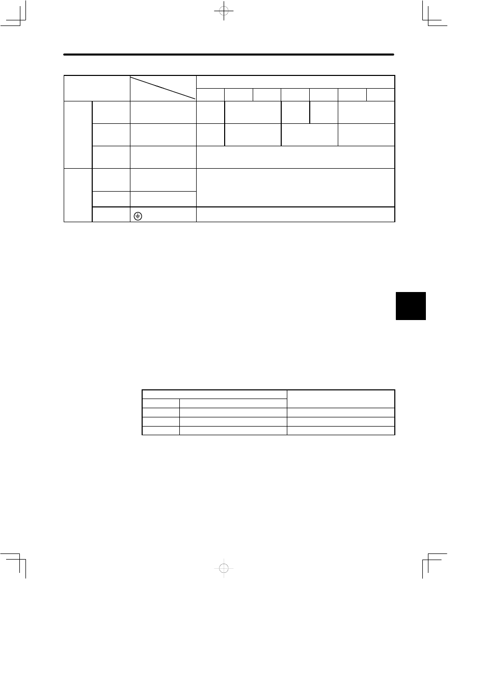
External
Terminal Name
SGDB Type
Terminal
Cable Size (mm
2
)
Terminal Name
Terminal
Symbol
30AD
44AD
50AD
60AD
75AD
1AAD
1EAD
On-line
Terminal
Main Circuit
Power Input
Terminal
R, S, T
HIV 3.5
or more
HIV 5.5 or more
HIV 8 or
more
HIV 14
or more
HIV 22 or more
Motor
Connection
Terminal
U, V, W
HIV 5.5
or more
HIV 8 or more
HIV 14 or more
HIV 22 or more
Control
Power Input
Terminal
r, t
HIV 1.25 or more
Off-line
Terminal
Control I/O
Signal
Connector
1CN
Core of twisted pair or twisted pair shield wires: 0.12 mm
2
or more
Outside dimensions of tinned annealed copper twisted wires:
max. Ø16 (for 1CN), max. Ø11 (for 2CN)
PG Signal
Connector
2CN
(
),
(
)
Ground
Terminal
HIV 2.0 or more
Note
1) Cable size selection conditions: Ambient temperature 40_C, 3 wires per bundle, and
rated current flowing
2) For the main circuit, use cables with a dielectric strength of 600 V or more.
3) If the cables are laid in a duct (rigid PVC tube or metal pipe), allow for the reduced current
rating applicable to the cables.
4) If the ambient temperature (inside the control panel) is high, cables sheathed with ordi-
nary vinyl will be easily subject to heat deterioration and become unusable in a short pe-
riod of time. To prevent this, always use heat resistant cables.
The types of cable are shown in the table below. Use it in combination with the tables.
Cable Type
Conductor Allowable Temperature
C
Symbol
Name
p
_
C
PVC
Normal vinyl cable
---
IV
600 V vinyl cable
60
HIV
Temperature-resistant vinyl cable
75
Note
1) Use cable with 600 V min. rating for main circuits.
2) Consider allowable current reduction ratio if cables are bundled in PVC or metal ducts.
3) Use temperature-resistant cable under high ambient or panel temperature where nor-
mal vinyl cables rapidly deteriorate.
5