Yaskawa SGDB User Manual
Page 55
2.4 Conducting a Test Run
43
J
Using the Digital Operator
Operate the motor with the Digital Operator. Check
that the motor runs normally.
Refer to Section 4.2.2 Operation Using the Digital
Operator.
J
Connecting Signal Lines
Connect connector 1CN as follows:
1. Turn the power OFF.
2. Connect connector 1CN.
3. Turn the power ON again.
J
Checking Input Signals.
Check the input signal wiring in monitor mode.
For the checking method, refer to Section
4.1.7 Operation in Monitor Mode.
• Checking method
Turn each connected signal line ON and
OFF to check that the monitor bit display
changes accordingly.
Input Signal
ON/OFF
Monitor Bit Display
High level or open
OFF
Extinguished
0 V level
ON
Lit
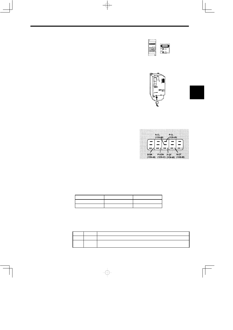
If the signal lines below are not wired correctly, the motor fails to rotate. Always wire
them correctly. (If signal lines are not to be used, short them as necessary.)
P-OT
1CN-42
Motor can rotate in forward direction when this input signal is at 0 V.
N-OT
1CN-43
Motor can reverse when this input signal is at 0 V.
S-ON
1CN-40
Servo is turned ON when this input signal is at 0 V. However, leave
the servo in OFF status.
2
Operation by Digital Operator
If an alarm occurs, the power supply
circuit, motor wiring, or encoder
wiring is incorrect.
Connect
connector
1CN.
Internal status bit display
(Un-05, Un-06)
Example of
Un-05
The memory switch can be
used to
eliminate the need
for
external short-circuits in
wiring (see pages 56 and
131).