Yaskawa SGDB User Manual
Page 165
3.8 Special Wiring
153
J
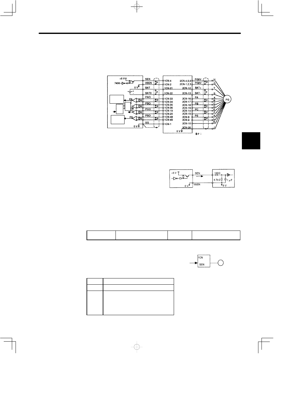
Standard Connection Diagram for an Absolute Encoder Mounted on a Servomotor
• Interface Circuit
Host controller
Battery
Line receiver
Clear
Up/
down
count-
er
SERVOPACK
SGMj servomotor
Absolute encoder
Represents twisted pair wires
Serial
interface
circuit
De-
cod-
er
Serial
interface
circuit
Line Receiver Used:
SN75175 or MC3486 manufactured by Texas Instruments Inc.
Termination Resistor R:
220 to 470 Ω
/PAO
/PBO
/PCO
/PSO
/PA
/PB
/PC
/PS
PS, /PS, PSO and /PSO are for 12-bit absolute encoders only.
SEN signal
• The SEN signal must be set at high level af-
ter at least three seconds after the power is
turned ON.
• When the SEN signal is changed from low
level to high level, +5 V is applied to the ab-
solute encoder, and serial data and initial in-
cremental pulses are transmitted.
• The motor is not turned ON until these operations are complete, regardless of the servo
ON signal (/S-ON).
J
Memory Switch to Determine Whether to Use Input Signal SEN
Cn-01 Bit 1
Use of SEN Input Signal
Factory
Setting: 0
For Speed/Torque Control
and Position Control
This memory switch is used to determine whether
to use input signal SEN (1CN-4).
This memory switch is available for absolute en-
coders only (not for incremental encoders).
Setting
Meaning
0
Uses SEN signal.
1
Does not use SEN signal.
(The SGDB SERVOPACK always
assumes that the SEN signal is at high
level, regardless of the actual signal
level.)
3
Electrical Specifications
Host controller
At high level
Approx. 1mA
7406 or
equivalent
SGDB
SERVOPACK
• A PNP transistor is recommended.
• Signal level High level: Min. 2.5 V
Low level: Max. 0.8 V
1CN-4
1CN-2
SERVOPACK
Servomotor
Absolute encoder
-4