8 handling of power loss – Yaskawa SGDB User Manual
Page 153
3.7 Forming a Protective Sequence
141
Preset
Value
Function
0
/COIN, /V-CMP
(Can be allocated to 1CN-25 and 1CN-26 only.)
1
/TGON
2
/S-RDY
3
/CLT
4
/BK
5
Overload warning
6
Overload alarm
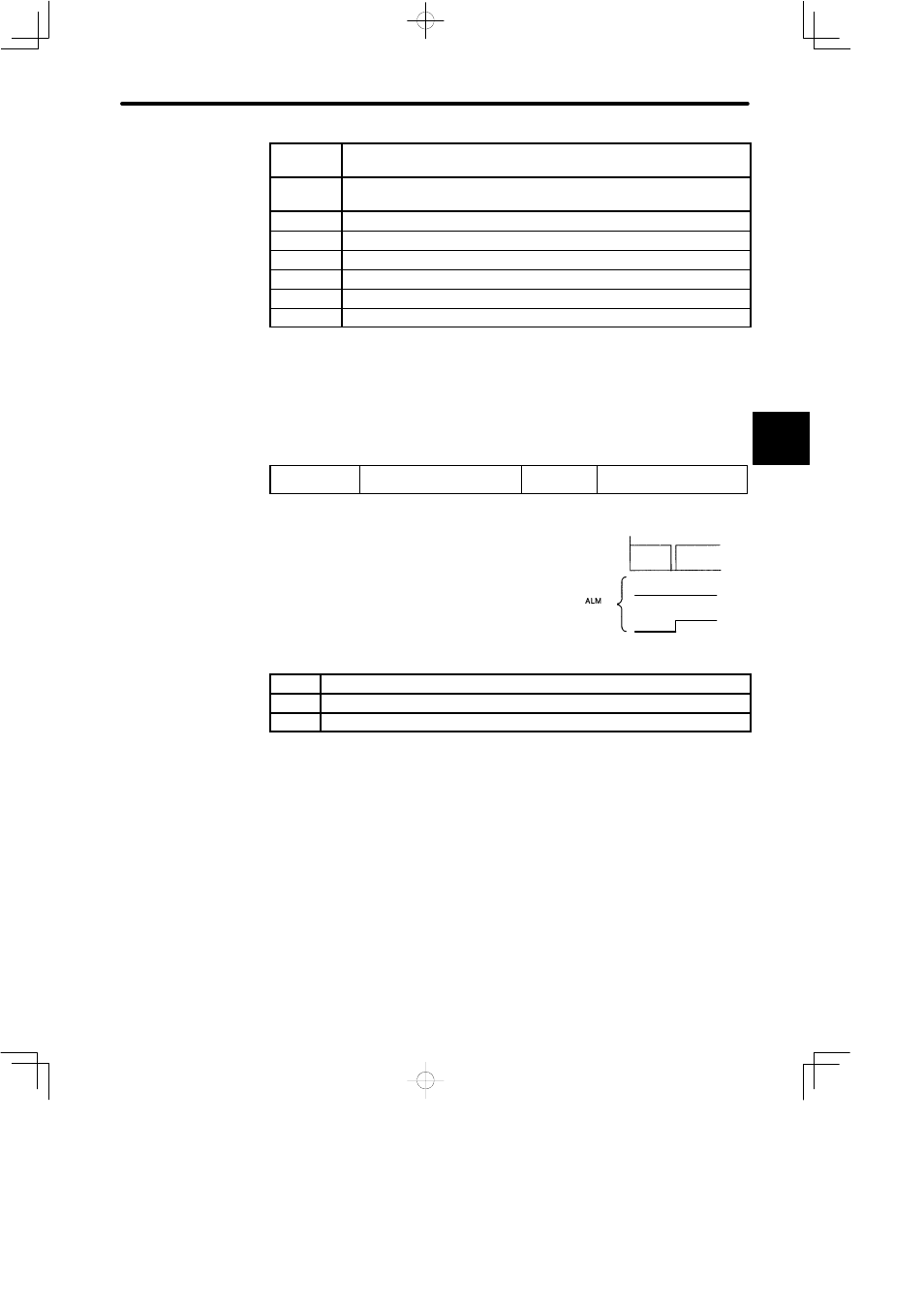
3.7.8 Handling of Power Loss
Use the following memory switch to specify whether to output a servo alarm when power
loss occurs.
Cn-01 Bit 5
Operation to Be Performed at
Recovery from Power Loss
Factory
Setting: 0
For Speed/Torque Control
and Position Control
If the SGDB SERVOPACK detects instantaneous
voltage drop in power supply, it can output servo
alarm A.F3 to prevent a hazardous situation. This
memory switch is used to specify whether to out-
put this alarm.
Setting
Meaning
0
Does not output a servo alarm after recovery from power loss.
1
Outputs a servo alarm after recovery from power loss.
Normally, set this memory switch to 0. If the /S-RDY signal is not to be used, set the
memory switch to 1. The /S-RDY signal remains OFF while the main power supply is
OFF, regardless of the memory switch setting.
3
200 V
supply
voltage
Power loss
Cn-01 bit 5 = 0
Cn-01 bit 5 = 1
(1CN-31)
- Tag Generator (30 pages)
- MP3300iec (82 pages)
- 1000 Hz High Frequency (18 pages)
- 1000 Series (7 pages)
- PS-A10LB (39 pages)
- iQpump Micro User Manual (300 pages)
- 1000 Series Drive Option - Digital Input (30 pages)
- 1000 Series Drive Option - CANopen (39 pages)
- 1000 Series Drive Option - Analog Monitor (27 pages)
- 1000 Series Drive Option - CANopen Technical Manual (37 pages)
- 1000 Series Drive Option - CC-Link (38 pages)
- 1000 Series Drive Option - CC-Link Technical Manual (36 pages)
- 1000 Series Drive Option - DeviceNet (37 pages)
- 1000 Series Drive Option - DeviceNet Technical Manual (81 pages)
- 1000 Series Drive Option - MECHATROLINK-II (32 pages)
- 1000 Series Drive Option - Digital Output (31 pages)
- 1000 Series Drive Option - MECHATROLINK-II Technical Manual (41 pages)
- 1000 Series Drive Option - Profibus-DP (35 pages)
- AC Drive 1000-Series Option PG-RT3 Motor (36 pages)
- Z1000U HVAC MATRIX Drive Quick Start (378 pages)
- 1000 Series Operator Mounting Kit NEMA Type 4X (20 pages)
- 1000 Series Drive Option - Profibus-DP Technical Manual (44 pages)
- CopyUnitManager (38 pages)
- 1000 Series Option - JVOP-182 Remote LED (58 pages)
- 1000 Series Option - PG-X3 Line Driver (31 pages)
- SI-EN3 Technical Manual (68 pages)
- JVOP-181 (22 pages)
- JVOP-181 USB Copy Unit (2 pages)
- SI-EN3 (54 pages)
- SI-ET3 (49 pages)
- MECHATROLINK-III (35 pages)
- EtherNet/IP (50 pages)
- SI-EM3 (51 pages)
- 1000-Series Option PG-E3 Motor Encoder Feedback (33 pages)
- 1000-Series Option SI-EP3 PROFINET (56 pages)
- PROFINET (62 pages)
- AC Drive 1000-Series Option PG-RT3 Motor (45 pages)
- SI-EP3 PROFINET Technical Manual (53 pages)
- A1000 Drive Option - BACnet MS/TP (48 pages)
- 120 Series I/O Modules (308 pages)
- A1000 12-Pulse (92 pages)
- A1000 Drive Software Technical Manual (16 pages)
- A1000 Quick Start (2 pages)
- JUNMA Series AC SERVOMOTOR (1 page)
- A1000 Option DI-101 120 Vac Digital Input Option (24 pages)