Yaskawa SGDB User Manual
Page 179
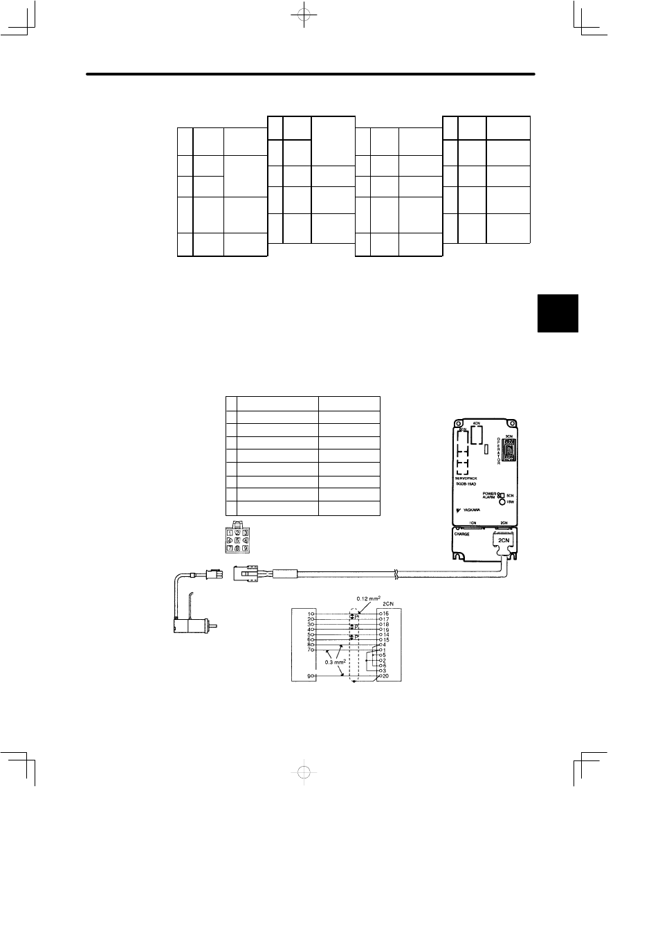
3.8 Special Wiring
167
2CN Terminal Layout
1
PG0V
11
2
PG0V
PG power sup-
1
PG0V
PG power sup-
12
BAT
Battery (+) (for
b l t
11
2
PG0V
PG power sup-
ply 0 V
3
PG0V
PG power sup-
ply 0 V
12
BAT +
Battery (+) (for
absolute en-
coder only)
13
BAT −
Battery (−) (for
absolute en-
4
PG5V
3
PG0V
14
PC
PG input
13
BAT −
absolute en-
coder only)
4
PG5V
PG power sup-
5
PG5V
PG power sup-
14
PC
PG input
phase C
15
/PC
PG input
6
PG5V
PG power sup-
ply +5 V
5
PG5V
PG power sup-
ply +5 V
16
PA
PG input
15
/PC
PG input
phase C
6
PG5V
Rotation direc-
16
PA
PG input
phase A
PG input
8
PS
PG input
phase S (for
7
DIR
Rotation direc-
tion input
18
PB
PG input
17
/PA
PG input
phase A
8
PS
phase S (for
absolute en-
coder only)
9
PS
PG input
phase S (for
absolute en-
18
PB
PG input
phase B
19
/PB
PG input
phase B
10
9
PS
absolute en-
coder only)
20
FG
F
d
19
/PB
phase B
10
20
FG
Frame ground
D
SERVOPACK Side
Connector type: 10220-52A2JL (manufactured by 3M)
D
Cable Side
Connector type: 10120-3000VE (manufactured by 3M)
Connector case type: 10320-52A0-008 (manufactured by 3M)
J
Connectors for Incremental Encoder
[SGM and SGMP series]
Blue
White/Blue
Yellow
White/Yellow
Green
White/Green
Red
Black
Green/Yellow
Items to be Prepared by Customer
Case:
10320-52A0-008
(manufactured by 3M)
Connector:
10120-3000VE
(manufactured by 3M)
Items to be Prepared by Customer
Cap:
172161-1
Socket: 170361-1 (chain type) or
170365-1 (loose type)
1
Channel A output
Blue
2
Channel /A output
Blue/Black
3
Channel B output
Yellow
4
Channel /B output
Yellow/Black
5
Channel C output
Green
6.
Channel /C output
Green/Black
7
0 V (power supply)
Gray
8
+5 V (power supply)
Red
9
Frame ground (FG)
Orange
3