HEIDENHAIN TNC 407 (280 580) User Manual User Manual
Page 70
4-11
TNC 425/TNC 415 B/TNC 407
4
Programming
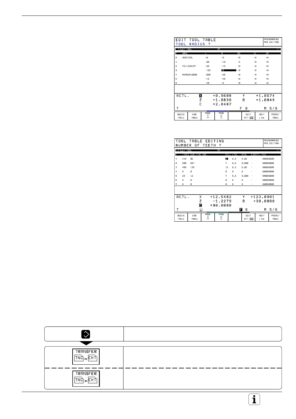
Fig. 4.6:
Left part of the tool table
Fig. 4.7:
Right part of the tool table
Tool data in tables
The following information can be entered in tool
tables:
• Tool radius and tool length: R, L
• Curvature radius of the tool point for three-
dimensional tool compensation: R2
For graphic display of machining with a spherical
cutter, enter R2 = R.
• Oversizes (delta values) for tool radii and tool
lengths: DR, DR2, DL
• Length of the tool cutting edge: LCUTS
• Maximum plunge angle: ANGLE
• Tool name: NAME
• Maximum and current tool life: TIME1, TIME2,
CUR.TIME
• Number of a Replacement Tool: RT
• Tool Lock: TL
• Tool comment: DOC
• Information on this tool for the Programmable
Logic Control (PLC — adapts the TNC to the
machine tool): PLC
The TNC needs the following tool data for automat-
ic tool measurement:
• Number of teeth: CUT
• Wear tolerance for tool length: LTOL
• Wear tolerance for tool radius: RTOL
• Cutting direction for dynamic tool measurement:
DIRECT
• Offset of the tool from center of stylus to
center of tool: TT:R-OFFS
Default value: Tool radius R
• Offset of the tool from top of stylus to the tool
tip:
TT:L-OFFS
Default value: 0
• Breakage tolerance for tool length: LBREAK
• Breakage tolerance for tool radius: RBREAK
A general user parameter (MP7266) defines which
data can be entered in the tool table and in which
sequence the data is displayed.
The sequence of the information in the tool table
shown in the illustrations to the right is only one
example out of many possibilities.
If all the information in a table no longer fits on one
screen, this is indicated with a ">>" or "<<" symbol
in the line with the table name.
EXT
To read-out or read-in a tool table (see page 10-2):
Select external data input/output directly from the table.
Read-out the table.
Read-in the table (only possible if EDIT ON is selected).