HEIDENHAIN TNC 407 (280 580) User Manual User Manual
Page 174
5-75
TNC 425/TNC 415 B/TNC 407
5
Programming Tool Movements
Enter the feed rate, for example 750 mm/min.
Contour point tables for defining the digitizing range
If you are using the measuring touch probe system, you can create point
tables to define the contour of the desired digitizing range in the POSI-
TIONING WITH MDI mode of operation. You can enter the points in the
table by:
• Capturing the points by teach-in programming, or
• Having the TNC generate the points automatically.
• You can enter up to 893 points in a contour point table.
• The digitizing range is defined by straight lines connecting the programmed points. The last point in the table is
again connected to the first point in the table by a straight line.
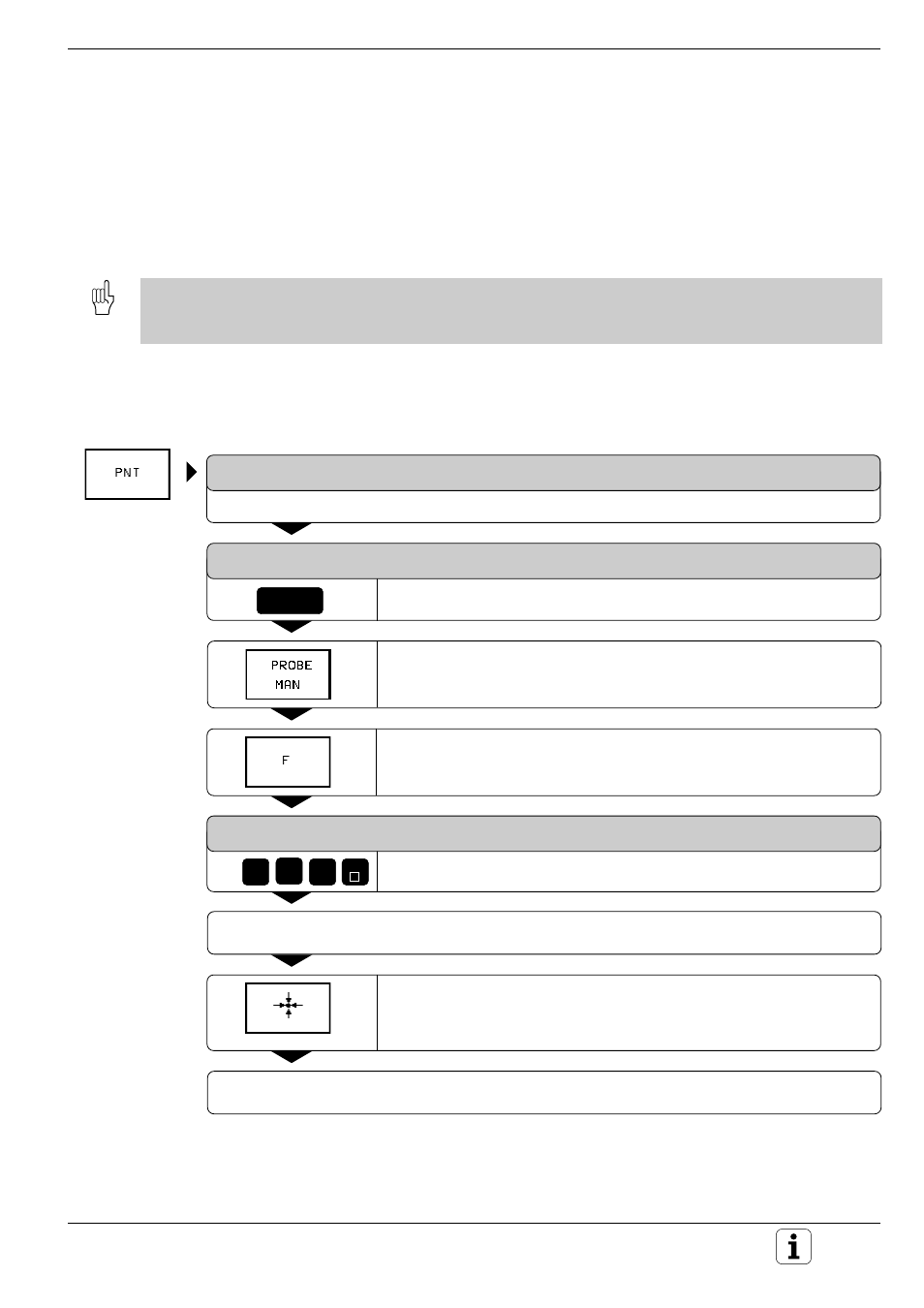
Capturing points manually by teach-in programming
After inserting the measuring touch probe into the spindle and locking it
mechanically, press the PNT soft key to select a point table:
FILE NAME =
Enter any desired file name.
MM=ENT / INCH=NOENT
ENT
Capture the points manually.
Indicate whether the dimensions will be entered in millimeters or
inches.
If necessary, enter the feed rate at which the measuring touch probe
should react to a stylus deflection.
FEED RATE = 200
7
5
0
e.g.
END
Move the touch probe to the first point of the digitizing range to be scanned by deflecting the stylus
manually in the desired direction.
Press the soft key for actual position capture. The TNC enters the X, Y
and Z coordinates in the point table. Only the coordinates of the
probing plane are evaluated for determining the digitizing range.
Move the touch probe to the next contour point of the desired range and capture the actual position.
Repeat this process until the entire digitizing range has been defined.