HEIDENHAIN TNC 407 (280 580) User Manual User Manual
Page 265

8-58
8
Cycles
TNC 407/TNC 415 B/TNC 425
WORKING PLANE (Cycle 19) (not for TNC 407)
The functions for tilting the working plane are adapted to the TNC and the machine by the machine manufacturer.
The TNC supports machine tools with swivel heads (the tool is tilted)
and/or tilting tables (the workpiece is tilted).
The program is written as usual in a main plane, such as the X/Y plane, but
is executed in a plane that is tilted relative to the main plane.
Typical applications:
• Oblique holes
• Contours in an oblique plane
There are two ways to tilt the working plane:
• 3D ROT soft key in the MANUAL OPERATION and ELECTRONIC
HANDWHEEL operation modes (see page 2-9)
• Cycle 19 WORKING PLANE in the part program
The TNC functions for tilting the working plane are coordinate transforma-
tions. The transformed tool axis (i.e., as calculated by the TNC) always
remains parallel to the actual tool axis (the axis being positioned). The
working plane is always perpendicular to the direction of the tool axis.
When tilting the working plane, the TNC differentiates between two
machine types:
• Machines with tilting tables
• Machines with swivel heads
For machines with tilting tables:
• You must bring the workpiece into the desired position for machin-
ing by positioning the tilting table, for example with an L block.
• The position of the transformed tool axis does not change in relation
to the machine-based coordinate system. Thus for example if you
rotate the swivel table – and therefore the workpiece – by 90°, the
coordinate system does not rotate. If you press the Z+ axis
direction button in the MANUAL OPERATION mode, the tool moves
in Z+ direction.
• In calculating the transformed coordinate system the TNC considers
only the mechanically influenced offsets of the particular tilting table
(the so-called "translational" components).
For machines with swivel heads:
• You must bring the tool into the desired position for machining by
positioning the swivel head, for example with an L block.
• The position of the transformed tool axis (like the position of the tool)
changes in relation to the machine-based coordinate system. Thus
for example if you rotate the swivel head – and therefore the tool – in
the B axis by +90°, the coordinate system rotates also. If you
press the Z+ axis direction button in the MANUAL OPERATION
mode, the tool moves in X+ direction of the machine-based coordi-
nate system.
• In calculating the transformed coordinate system the TNC considers
both the mechanically influenced offsets of the particular swivel head
(the so-called "translational" components) and the offsets caused by
tilting of the tool (3D tool length compensation).
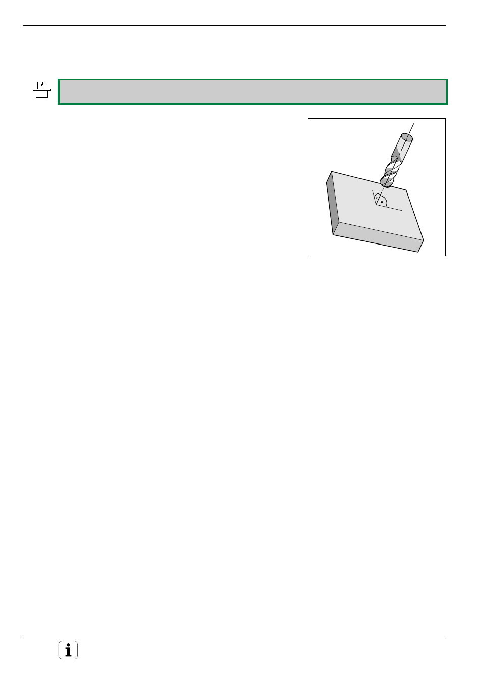
Fig. 8.56:
Pre-positioning the tool
perpendicular to tilted plane
