HEIDENHAIN TNC 407 (280 580) User Manual User Manual
Page 142

5–43
TNC 425/TNC 415 B/TNC 407
Contours – FK Free Contour Programming
5
Programming Tool Movements
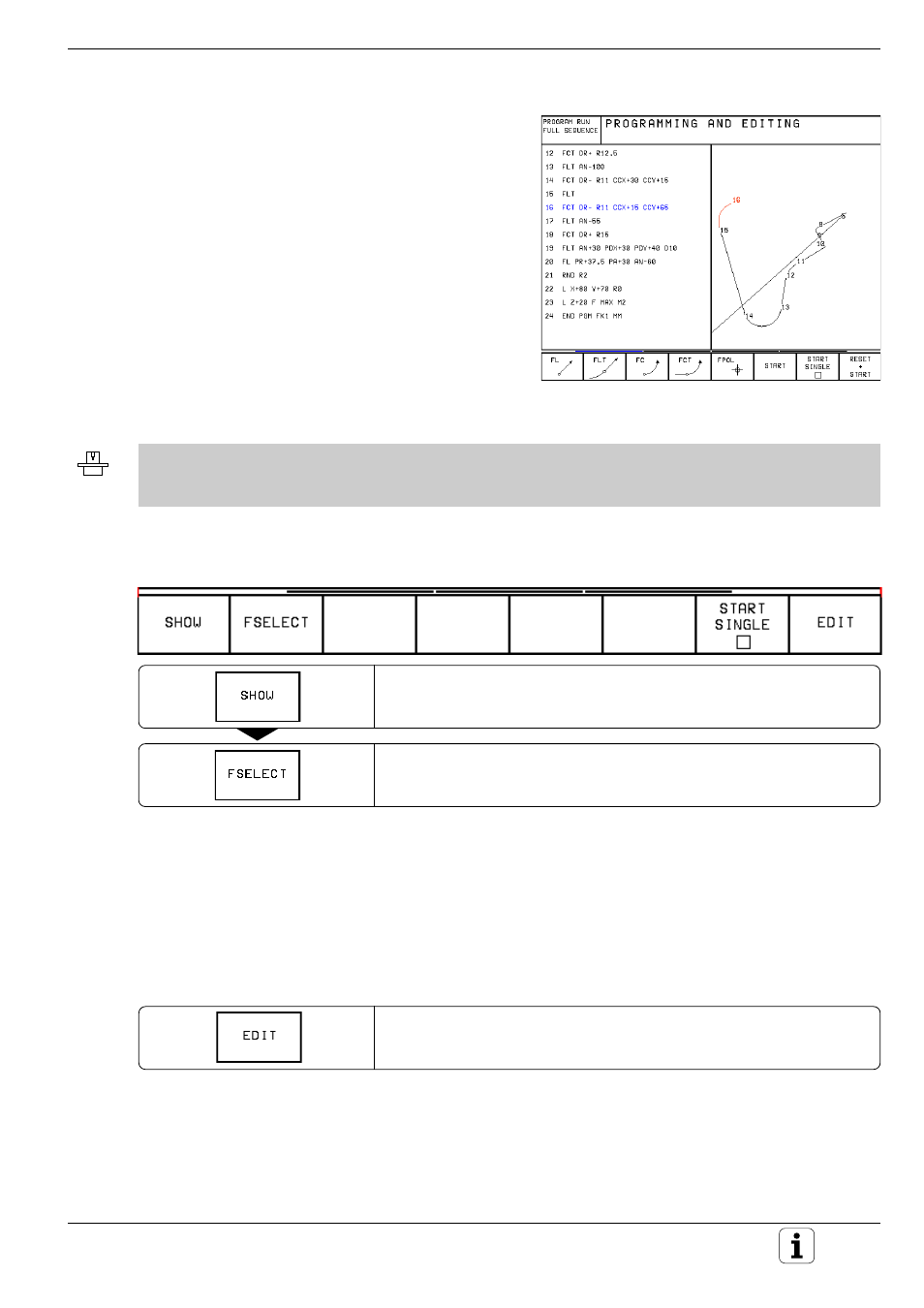
Fig. 5.46:
FK programming with interactive graphics
Interactive graphics during FK programming
You can use two-dimensional contour-line graphics
as an aid during FK programming. The screen
shows the contour elements as you program them
and offers you possible solutions when the contour
is not yet fully defined.
The programmed contour elements are displayed in
various colors (see fold-out of the front cover):
White:
The contour element is fully defined.
Green:
The entered data describes a limited
number of possible solutions.
Red:
The entered data could describe an
infinite number of possible solutions.
• The machine tool builder may use other colors for the interactive graphics.
• NC blocks from a program that you called with PGM CALL (see page 6-8) are displayed in another color, which
is defined by machine parameter.
The following soft key row appears if the entered data permit a limited
number of possible solutions:
Show the possible solutions described by the entered data.
Select the solution that matches the drawing.
Use the SHOW and FSELECT functions to choose a proposed (green)
contour element. The element then appears white on the screen.
Select the green contour elements (ambiguous data) as soon as possible.
In this way you can reduce the ambiguity of subsequent elements.
If you do not yet wish to select an element, press the EDIT soft key:
Enter data for subsequent contour elements.
