Incremental dimensions, Yx z, Absolute workpiece positions – HEIDENHAIN TNC 407 (280 580) User Manual User Manual
Page 16: Incremental workpiece positions
TNC 425/TNC 415 B/TNC 407
1-15
1
Introduction
Fig. 1.17:
Definition of position ➀ through
absolute coordinates
Fig. 1.18:
Definition of positions ➁ and ➂
through incremental coordinates
Y
X
Z
1
20
10
Z=15mm
X=20mm
Y=10mm
15
I
Z=–15mm
Y
X
Z
2
10
5
5
15
20
10
10
I
X=10mm
I
Y=10mm
3
0
0
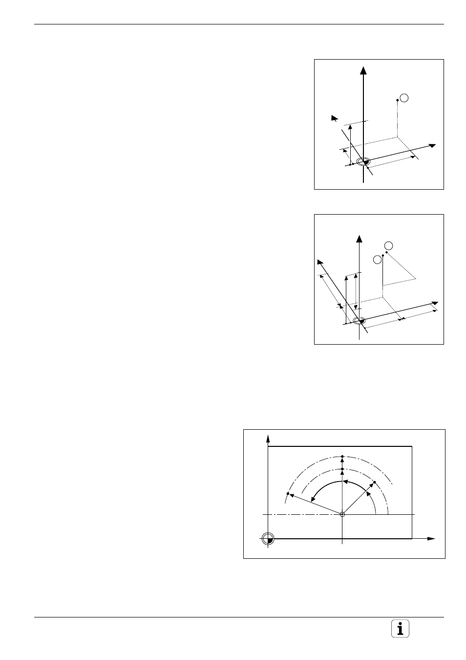
Fig. 1.19:
Incremental dimensions in polar coordinates (designated
with an "I")
X
Y
10
CC
0
°
30
PR
PR
PR
+IPR
+IPA
+IPA
PA
Absolute workpiece positions
Each position on the workpiece is clearly defined by its absolute coordi-
nates.
Example:
Example:
Example:
Example:
Example:
Absolute coordinates of the position ➀:
X = 20 mm
Y = 10 mm
Z = 15 mm
If you are drilling or milling a workpiece according to a workpiece drawing
with absolute coordinates, you are moving the tool to the coordinates.
Incremental workpiece positions
A position can be referenced to the previous nominal position: i.e. the
relative datum is always the last programmed position. Such coordinates
are referred to as incremental coordinates (increment = “growth”), or
also incremental or chain dimensions (since the positions are defined as a
chain of dimensions). Incremental coordinates are designated with the
prefix I.
Example: Incremental coordinates of the position ➂
referenced to position ➁
Absolute coordinates of the position ➁:
X = 10 mm
Y = 5 mm
Z = 20 mm
Incremental coordinates of the position ➂:
IX = 10 mm
IY = 10 mm
IZ = –15 mm
If you are drilling or milling a workpiece according to a workpiece drawing
with incremental coordinates, you are moving the tool by the coordinates.
An incremental position definition is therefore a specifically relative
definition. This is also the case when a position is defined by the
distance-to-go to the target position (here the relative datum is located at
the target position). The distance-to-go has a negative sign if the target
position lies in the negative axis direction from the actual position.
The polar coordinate system can also express both
types of dimensions:
• Absolute polar coordinates always refer to the
pole (CC) and the reference axis.
• Incremental polar coordinates always refer to
the last programmed nominal position of the
tool.