Tch probe 8.0 line, Yx z – HEIDENHAIN TNC 407 (280 580) User Manual User Manual
Page 316
9-49
TNC 425/TNC 415 B/TNC 407
9
3D Touch Probe Systems
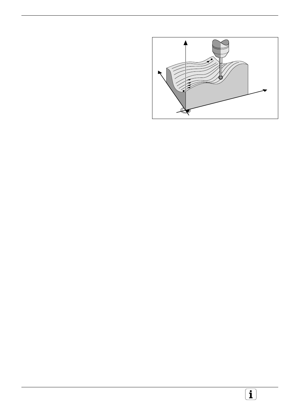
Fig. 9.31
Digitizing a 3D contour with the LINE cycle
Digitizing with the TS 120 Touch Probe
Y
X
Z
Line-by-line digitizing with cycle 8 LINE
The LINE cycle scans and digitizes a 3D contour in
a series of parallel lines. This process is particularly
useful for digitizing relatively flat surfaces which are
to be machined without prior evaluation of the data
resulting from digitizing.
In cycle 8 LINE, the touch probe moves in the
positive or negative direction of the axis entered
under DIRECTION. When the touch probe reaches
the MAX coordinate on this axis, it returns to
CLEARANCE HEIGHT. It then moves at rapid
traverse back to the beginning of the next line and
from there in the negative Z direction to the
HEIGHT FOR FEED RATE DECREASE. From this
point it continues moving at the probing feed rate
until it contacts the 3D contour. This process
repeats itself until the entire range has been
scanned.
Once the entire range is scanned, the touch probe
returns to the CLEARANCE HEIGHT.
Starting position
• Positive or negative MAX point coordinates in the programmed LINE
DIRECTION (depending on the digitizing direction)
• MIN point coordinates from cycle 5 RANGE of the programmed
column
• Z coordinate = CLEARANCE HEIGHT
Contour approach
The touch probe moves in the negative Z direction toward the model.
When it makes contact, the TNC stores position coordinates.
Input data
• LINE DIRECTION
Coordinate axis of the X/Y plane parallel to which the touch probe
scans the model. The algebraic sign determines the starting point and
the direction in which the touch probe begins scanning the model.
The digitizing direction at the same time defines whether the subse-
quent machining operation is performed by up-cut or climb milling.
• HEIGHT FOR FEED RATE DECREASE
Z coordinate at which the touch probe feed rate is reduced from rapid
traverse to the probing feed rate at the beginning of each line.
Input range: –99999.9999 to +99999.9999
• LIMIT IN NORMAL LINES DIRECTION
Distance by which the touch probe lifts off the model surface after
each deflection of the stylus during scanning.
Input range: 0 to 5 mm
Recommended input value: Enter an input value between half the
PROBE POINT INTERVAL and the PROBE POINT INTERVAL. The
smaller the ball tip radius, the larger the LIMIT IN NORMAL LINES
DIRECTION should be programmed.
• LINE SPACING
The offset by which the probe moves at the end of each line before
scanning the next line.
Input range: 0 to 5 mm
• MAX. PROBE POINT INTERVAL
Maximum spacing between consecutive digitized positions.
Input range: 0.02 to 5 mm