Yx z – HEIDENHAIN TNC 407 (280 580) User Manual User Manual
Page 241
8-34
8
Cycles
TNC 407/TNC 415 B/TNC 425
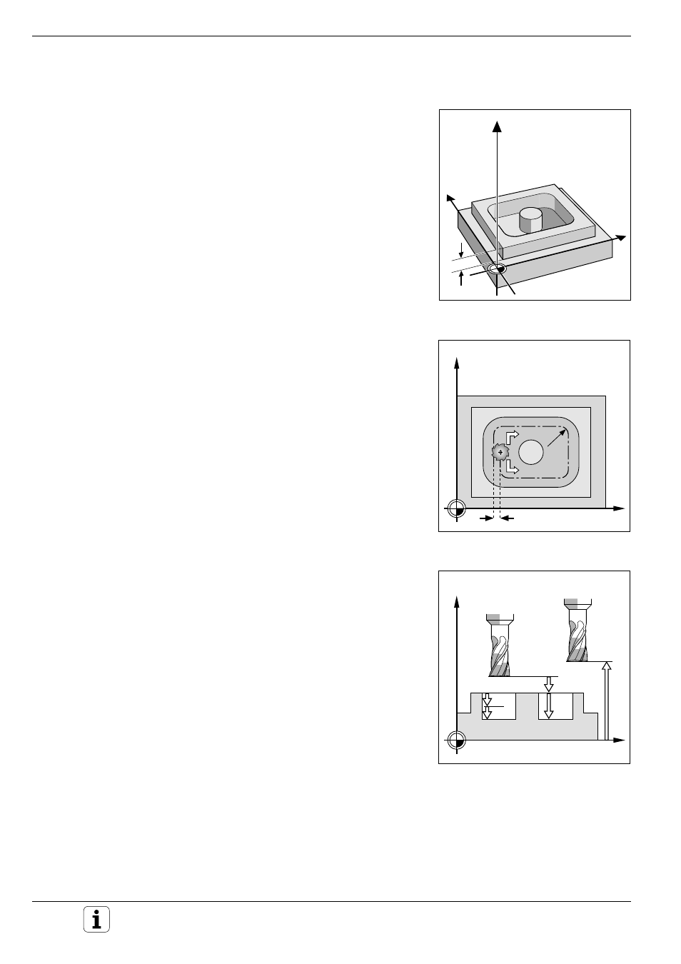
Fig. 8.38:
Distance and infeed parameters
Fig. 8.37:
Direction of rotation Q9 and
stepover factor k
Fig. 8.36: Workpiece surface coordinates Q5
Y
X
Z
Q5
X
Z
Q1
Q6
Q10
Q7
X
Y
k
Q9=–1
Q9=+1
Q8
CONTOUR DATA (Cycle 20)
Application
Machining data for the subprograms describing the subcontours are
entered in cycle 20. They are valid for the cycles 21 to 24.
Input data
• MILLING DEPTH Q1:
Distance between workpiece surface and pocket floor.
• PATH OVERLAP FACTOR Q2:
Q2 * tool radius = stepover factor k.
• ALLOWANCE FOR SIDE Q3:
Finishing allowance in the working plane.
• ALLOWANCE FOR FLOOR Q4:
Finishing allowance in the tool axis.
• WORKPIECE SURFACE COORDINATES Q5:
Absolute coordinates of the workpiece surface referenced to the
workpiece datum.
• SETUP CLEARANCE Q6:
Distance between the tool tip and the workpiece surface.
• CLEARANCE HEIGHT Q7:
Absolute height at which the tool cannot collide with the workpiece (for
intermediate positioning and retraction at the end of the cycle).
• ROUNDING RADIUS Q8:
Inside “corner” rounding radius.
• DIRECTION OF ROTATION Q9:
Direction of rotation for pockets
clockwise
(Q9 = –1 up-cut milling for pocket and island)
counterclockwise
(Q9 = +1 climb milling for pocket and island).
The sign for milling depth Q1 determines the working direction (negative
sign means negative working direction).
Activation
Cycle 20 is immediately effective upon definition.
The machining parameters can be checked during a program interruption
and can be overwritten, if required.
If the SL cycles are used in Q parameter programs, the cycle parameters
Q1 to Q14 must not be used as program parameters.