HEIDENHAIN TNC 407 (280 580) User Manual User Manual
Page 301
TNC 425/TNC 415 B/TNC 407
9-34
9
3D Touch Probe Systems
.
.
.
e.g.
0
ENT
5
e.g.
0
ENT
5
Resulting NC blocks:
TCH PROBE
17.0 CONTOUR LINES
TCH PROBE
17.1 TIME: 0 X+0 Y+0
TCH PROBE
17.2 ORDER: Y– / X–
TCH PROBE
17.3 F1000
MIN.L.SPAC: 0.2 L.SPAC: 0.5
PP.INT: 0.5 TOL: 0.1
e.g.
0
ENT
1
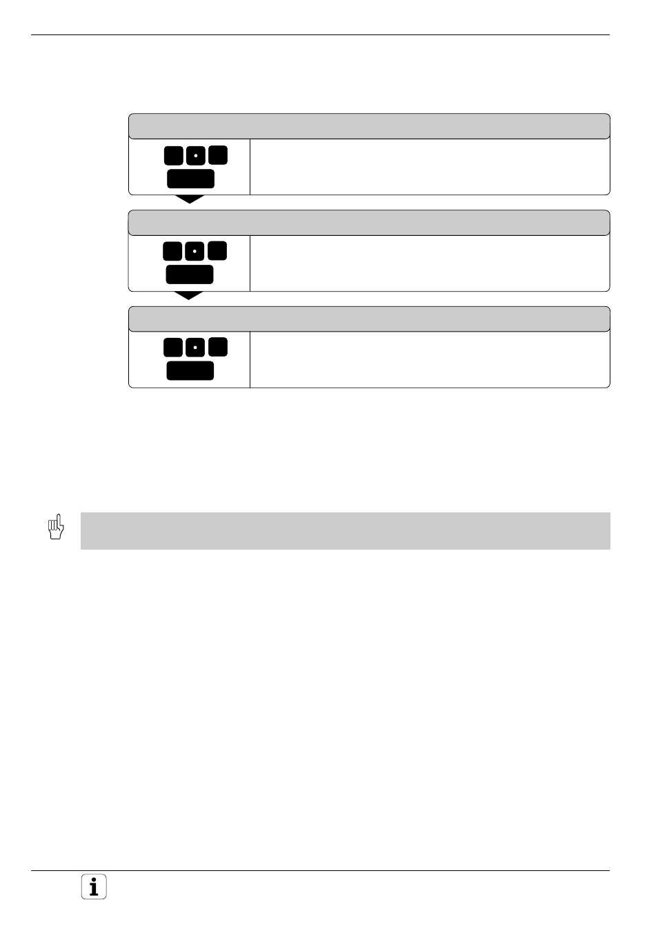
Digitizing with a Measuring Touch Probe
LINE SPACING AND DIRECTION ?
Enter the maximum line spacing, for example +0.5 mm. The alge-
braic sign determines the direction in which the probe moves to start
the next contour line.
MAX. PROBE POINT INTERVAL ?
Enter the maximum probe point interval, for example 0.5 mm.
TOLERANCE ?
Enter the diameter of the tubular tolerance zone, for example
0.1 mm.
Before cycle 17: CONTOUR LINES, the program must have a range defined in cycle 5: RANGE or cycle 15: RANGE
(TABLE).
- TNC 122 User Manual (63 pages)
- TNC 122 Technical Manual (70 pages)
- TNC 360 Service Manual (157 pages)
- TNC 416 Technical Manual (510 pages)
- TNC 335 Technical Manual (581 pages)
- TNC 360 User Manual (237 pages)
- TNC 360 ISO-Programmierung (2 pages)
- TNC 415 (280 540) User Manual (227 pages)
- TNC 370D (92 pages)
- TNC 416 (289 pages)
- TNC 415 (280 540) Technical Manual (752 pages)
- TNC 415 (259 96x) Service Manual (195 pages)
- iTNC 530 (340 420) Pilot (104 pages)
- TNC 407 (280 580) ISO Programming (333 pages)
- TNC 415 (280 540) Service Manual (252 pages)
- PT 880 Installation (112 pages)
- ND 100 User Manual (116 pages)
- ND 287 User Manual (147 pages)
- ND 280 Quick Start (12 pages)
- ND 200 (156 pages)
- ND 282 (10 pages)
- ND 287 Quick Start (26 pages)
- ND 282 B (39 pages)
- ND 281 A (44 pages)
- ND 281 B v.1 (53 pages)
- ND 281 B v.2 (65 pages)
- ND 221 v.2 (10 pages)
- ND 231 B v.2 (56 pages)
- ND 231 B v.1 (44 pages)
- ND 221 B v.2 (45 pages)
- ND 550 v.2 (8 pages)
- NDP 560 (10 pages)
- ND 523 (93 pages)
- ND 570 (8 pages)
- ND 750 v.2 (46 pages)
- ND 760 v.3 (72 pages)
- ND 770 v.1 (40 pages)
- ND 770 v.3 (41 pages)
- ND 760 E (44 pages)
- IOB 49 (21 pages)
- NDP 960 (68 pages)
- ND 780 Installation (132 pages)
- ND 970 (47 pages)
- ND 1100 Quick Start (36 pages)