HEIDENHAIN TNC 407 (280 580) User Manual User Manual
Page 315

TNC 425/TNC 415 B/TNC 407
9-48
9
3D Touch Probe Systems
0
e.g.
ENT
5
0
e.g.
ENT
2
.
.
.
Digitizing with the TS 120 Touch Probe
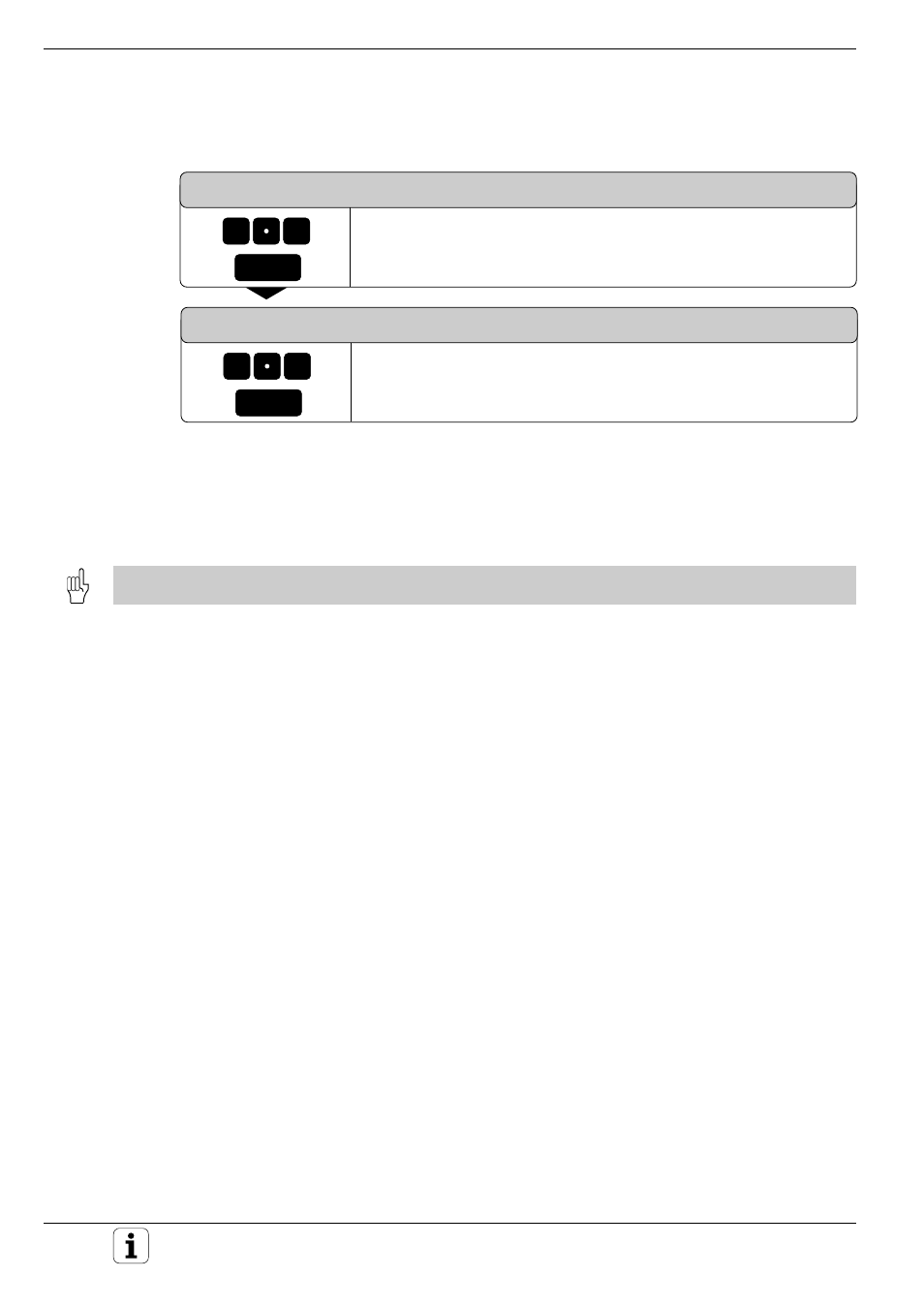
LINE SPACING AND DIRECTION ?
Enter the line spacing, for example +0.2 mm. The algebraic sign
determines the direction in which the probe moves to start the next
contour line.
MAX. PROBE POINT INTERVAL?
Enter the maximum probe point interval, for example 0.5 mm
Resulting NC blocks:
TCH PROBE 7.0
CONTOUR LINES
TCH PROBE 7.1
TIME: 0 X+0 Y+0
TCH PROBE 7.2
ORDER: Y– / X–
TCH PROBE 7.3
TRAVEL: 0.5 L.SPAC: +0.2
PP.INT: 0.5
Before cycle 7: CONTOUR LINES, the program must have a range defined in digitizing cycle 5: RANGE.
The TNC generates an NC part program from the digitized data. The
program name is entered in the scanning cycle RANGE.
During program execution, the tool radius determines the shape of the
machined contour.
When the tool radius equals the effective probe tip radius
The program can be run without any changes. The model that has been
scanned is reproduced.
When the tool radius does not equal the effective probe tip radius
The machined part is either smaller or larger than the model.
