Cl l – HEIDENHAIN TNC 407 (280 580) User Manual User Manual
Page 101

TNC 425/TNC 415 B/TNC 407
5-2
5
Programming Tool Movements
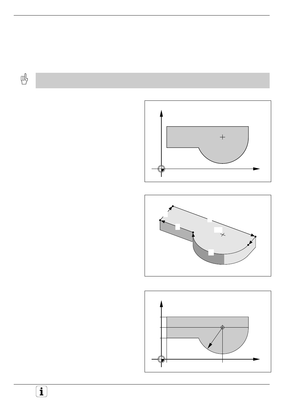
Fig. 5.2: Contour elements are programmed and executed in sequence
Fig. 5.1: A contour consists of straight lines and circular arcs
X
Y
L
L
CC
C
L
L
Fig. 5.3: This drawing is not dimensioned for conventional NC
X
Y
40
80
10
11
5
60
R 50
5.1 General Information on Programming Tool Movements
A tool movement is always programmed as
if the tool moves and the workpiece remains
stationary.
Before executing a part program, always pre-position the tool to prevent the possibility of damaging the
tool or the workpiece.
Path functions
Each element of the workpiece contour is entered
separately using path functions.
You enter:
• Straight lines
• Circular arcs
You can also program a combination of the two
(helical paths).
The contour elements are executed in sequence to
machine the programmed contour.
Free contour (FK) programming
With FK programming, you can create part pro-
grams easily in plain language dialog even if
the drawing is not dimensioned according to NC
standards.
FK programming also results in a contour consisting
of circular arcs and straight line segments. The
TNC uses the information you enter to calculate the
missing dimensions.
