Digitizing with a rotary axis – HEIDENHAIN TNC 407 (280 580) User Manual User Manual
Page 318
9-51
TNC 425/TNC 415 B/TNC 407
9
3D Touch Probe Systems
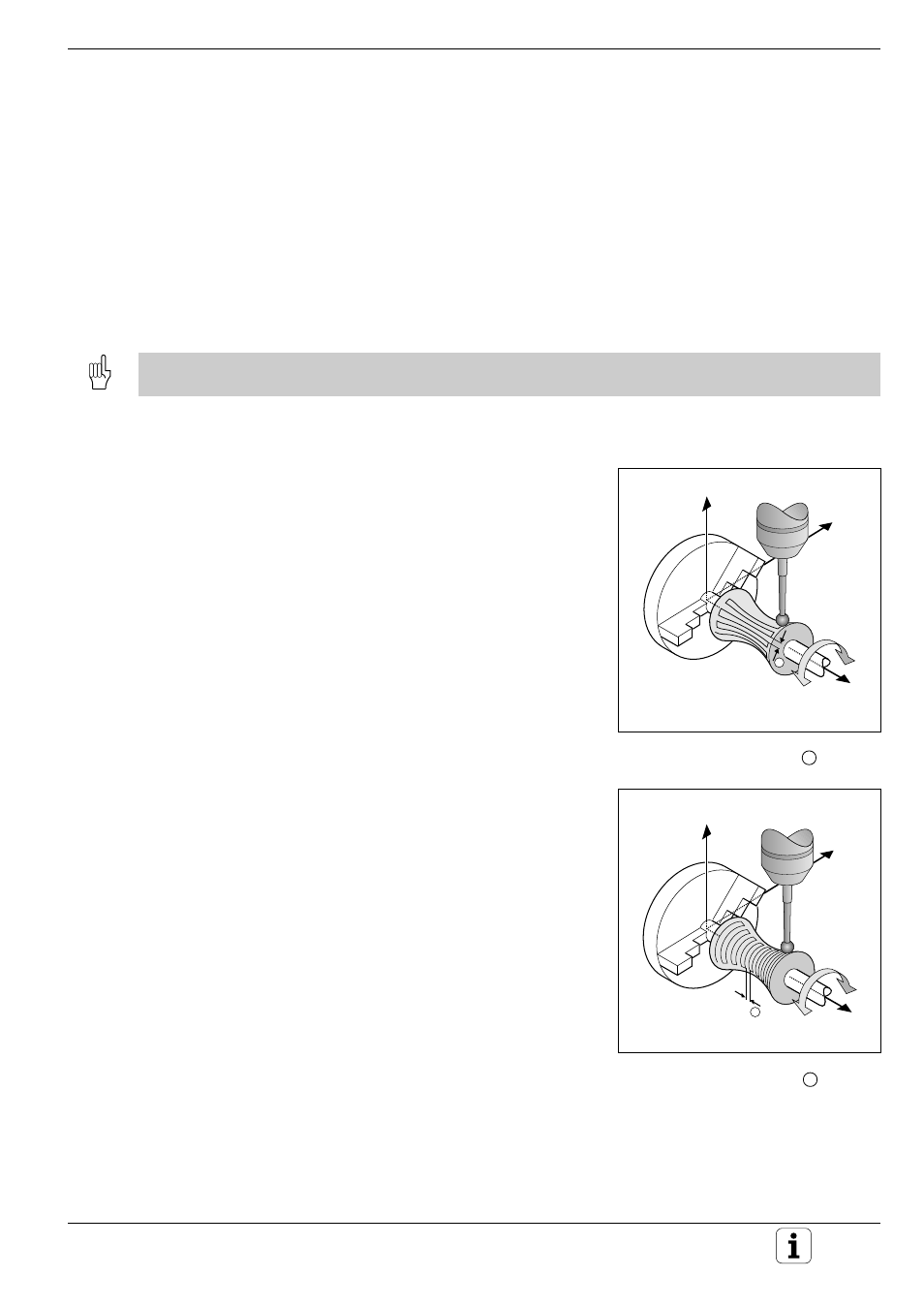
Fig. 9.33:
Line-by-line digitizing with a rotary
axis, line direction A; 1 : L.SPAC
Fig. 9.32:
Line-by-line digitizing with a rotary
axis, line direction X; 1 : L.SPAC
Z
Y
X
A
1
Z
Y
X
A
1
Digitizing with the TS 120 Touch Probe
Digitizing with a rotary axis
The digitizing feature supports rotary axes with the cycles MEANDER
(cycle 6), LINE (cycle 8) or CONTOUR LINE (cycle 7). Regardless of the
digitizing cycle used, the corresponding rotary axis must be entered in
the RANGE cycle. The TNC interprets the rotary axis input as values in
degrees.
Digitized data
The digitized data contains position information in the axes that are
identified in the RANGE cycle. A BLK FORM is not generated, since
rotary axes cannot be graphically simulated.
The display mode of the rotary axis (i.e. whether the display reduces the values to below 360° or not) must agree for
digitizing and for milling .
MEANDER cycle with a rotary axis
If you enter a linear axis in the input parameter
LINE DIRECTION the TNC moves the rotary axis
entered in the RANGE cycle by the line spacing
L.SPAC as soon as it reaches the end of the line. If
the line direction is the linear axis X, and L.SPAC is
in A, then the touch probe oscillates in the Z/X
plane.
If you define the line direction as a rotary axis, the
TNC moves the linear axis entered in the RANGE
cycle by the line spacing L.SPAC as soon as it
reaches the end of the line. If the line direction is
the rotary axis A, and L.SPAC is in the linear axis X,
then the touch probe oscillates in the Z/A plane.