HEIDENHAIN TNC 407 (280 580) User Manual User Manual
Page 223

8-16
8
Cycles
TNC 407/TNC 415 B/TNC 425
A
B
C
DR+
DR–
F
R
CIRCULAR POCKET MILLING (Cycle 5)
Process
• Circular pocket milling is a roughing cycle, in which the tool penetrates
the workpiece from the starting position (pocket center).
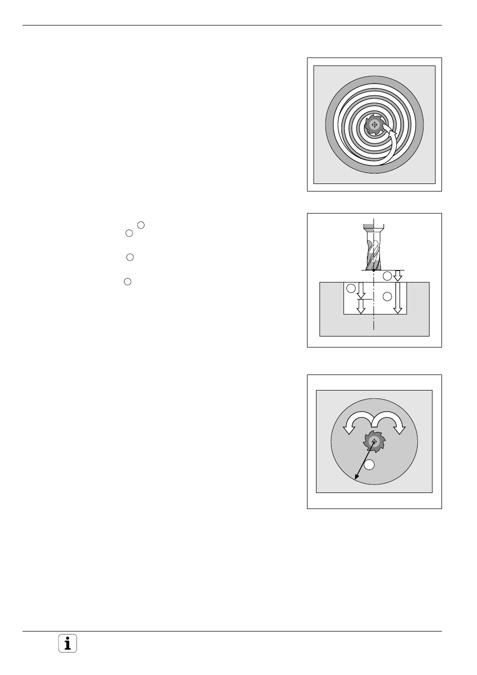
• The cutter subsequently follows a spiral path (shown in Fig. 8.10) at the
programmed feed rate. The stepover factor is determined by the value
k (see Cycle 4, RECTANGULAR POCKET MILLING: Calculations).
• The process is repeated until the programmed milling depth is reached.
• At the end of the cycle, the tool is retracted to the starting position.
Required tool
The cycle requires a center-cut end mill (ISO 1641), or pilot drilling at the
pocket center.
Input data
• SETUP CLEARANCE
A
• MILLING DEPTH
B
: pocket depth.
The algebraic sign determines the working direction (a negative value
means negative working direction).
• PECKING DEPTH
C
• FEED RATE FOR PECKING:
Traversing speed of the tool during penetration
• CIRCLE RADIUS
R
:
Radius of the circular pocket
• FEED RATE F:
Traversing speed of the tool in the machining plane
• DIRECTION OF THE MILLING PATH:
DR + :
climb milling with M3
DR – :
up-cut milling with M3
Fig. 8.11:
Cutter path for roughing-out
Fig. 8.12:
Distances and infeeds for
CIRCULAR POCKET MILLING
Fig. 8.13:
Direction of the cutter path
Starting Point
At cycle call with radius compensation R0, the tool must be positioned:
• at setup clearance over the workpiece surface in the tool axis
• at the center of the pocket in the working plane
