HEIDENHAIN TNC 407 (280 580) User Manual User Manual
Page 230
8-23
8
Cycles
TNC 407/TNC 415 B/TNC 425
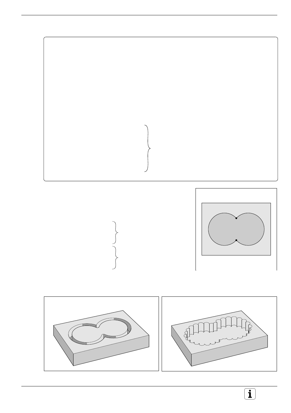
Fig. 8.19:
Outline is machined first
.
.
.
B
Right pocket
A
Left pocket
.
.
.
A
B
S
1
S
2
Cycle in a part program
0
BEGIN PGM OVERL1 MM
1
BLK FORM 0.1 Z X+0 Y+0 Z–20
2
BLK FORM 0.2 X+100 Y+100 Z+0
3
TOOL DEF 1 L+0 R+3
4
TOOL CALL 1 Z S1000
5
CYCL DEF 14.0 CONTOUR GEOM.
6
CYCL DEF 14.1 CONTOUR LABEL 1/2 .............. "List" of the contour subprograms
7
CYCL DEF 6.0 ROUGH-OUT .............................. Cycle definition ROUGH-OUT
8
CYCL DEF 6.1 SET UP +2 DEPTH –10
9
CYCL DEF 6.2 PECKG +5 F500 ALLOW +0
10
CYCL DEF 6.3 ANGLE +0 F500
11
L Z+100 R0 F MAX M6
12
L X+50 Y+50 F MAX M3 .................................... Pre-positioning X and Y, spindle on
13
L Z+2 F MAX M99 .............................................. Setup clearance Z, cycle call
14
L Z+100 F MAX M2 ............................................ Retract, rapid return to start of program
15
LBL 1
19
LBL 0
20
LBL 2
24
LBL 0
25
END PGM OVERL1 MM
Subprograms: Overlapping pockets
The pocket elements A and B overlap.
The control automatically calculates the points of intersection S1 and S2,
they do not have to be programmed.
The pockets are programmed as full circles.
15
LBL 1
16
L X+10 Y+50 RL
17
CC X+35 Y+50
18
C X+10 Y+50 DR+
19
LBL 0
20
LBL 2
21
L X+90 Y+50 RL
22
CC X+65 Y+50
23
C X+90 Y+50 DR+
24
LBL 0
25
END PGM OVERL1 MM
Depending on the control setup (machine parameters), machining starts
either with the outline or the surface:
Subprograms listed on page 8-23 and 8-24 can be
entered in these blocks
Fig. 8.18:
Points of intersection S
1
and S
2
of
pockets A and B
Fig. 8.20:
Surface is machined first