X +z +y – HEIDENHAIN TNC 407 (280 580) User Manual User Manual
Page 18
TNC 425/TNC 415 B/TNC 407
1-17
1
Introduction
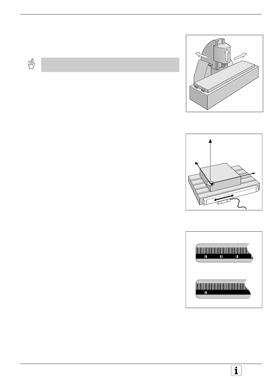
Fig. 1.22:
Linear position encoder, here for
the X axis
Fig. 1.23:
Linear scales: above with
distance-coded-reference marks,
below with one reference mark
Y
X
Z
Fig. 1.21:
On this machine the tool moves in
the Y and Z axes; the workpiece
moves in the positive X' axis.
+X
+Z
+Y
Programming tool movements
During workpiece machining, an axis position is changed either by moving
the tool or by moving the machine table on which the workpiece is fixed.
You always program as if the tool is moving and the workpiece is
stationary.
If the machine table moves, the axis is designated on the machine
operating panel with a prime mark (e.g. X’, Y’). Whether an axis designa-
tion has a prime mark or not, the programmed direction of axis movement
is always the direction of tool movement relative to the workpiece.
Position encoders
The position encoders – linear encoders for linear axes, angle encoders for
rotary axes – convert the movement of the machine axes into electrical
signals. The control evaluates these signals and constantly calculates the
actual position of the machine axes.
If there is an interruption in power, the calculated position will no longer
correspond to the actual position. When power is returned, the TNC can
re-establish this relationship.
Reference marks
The scales of the position encoders contain one or more reference marks.
When a reference mark is passed over, it generates a signal which
identifies that position as the machine axis reference point.
With the aid of this reference mark the TNC can re-establish the assign-
ment of displayed positions to machine axis positions.
If the position encoders feature distance-coded reference marks, each
axis need only move a maximum of 20 mm (0.8 in.) for linear encoders,
and 20° for angle encoders.