HEIDENHAIN TNC 407 (280 580) User Manual User Manual
Page 221
8-14
8
Cycles
TNC 407/TNC 415 B/TNC 425
A
B
C
E
D
DR+
DR–
F
k
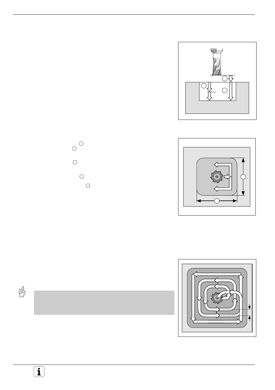
POCKET MILLING (Cycle 4)
Process
The rectangular pocket milling cycle is a roughing cycle, in which
• the tool penetrates the workpiece at the starting position (pocket
center)
• the tool subsequently follows the programmed path at the specified
feed rate (see Fig. 8.9)
The cutter begins milling in the positive direction of the axis of the longer
side. The cutter always starts in the positive Y direction on square pock-
ets. At the end of the cycle, the tool is retracted to the starting position.
Required tool/limitations
The cycle requires a center-cut end mill (ISO 1641), or pilot drilling at the
pocket center. The pocket sides are parallel to the axes of the coordinate
system.
Input data
• SETUP CLEARANCE
A
• MILLING DEPTH
B
:
The algebraic sign determines the working direction (a negative value
means negative working direction).
• PECKING DEPTH
C
• FEED RATE FOR PECKING:
Traversing speed of the tool during penetration.
• FIRST SIDE LENGTH
D
:
Pocket length, parallel to the first main axis of the machining plane.
• SECOND SIDE LENGTH
E
:
Pocket width
The signs of the side lengths are always positive.
• FEED RATE F:
Traversing speed of the tool in the machining plane.
• DIRECTION OF THE MILLING PATH:
DR + :
climb milling with M3
DR – :
up-cut milling with M3
• ROUNDING-OFF RADIUS:
RADIUS for the pocket corners.
If RADIUS = 0 is entered, the pocket corners will be rounded with the
radius of the cutter.
Calculations
The stepover factor k is calculated as follows:
k = K x R
K:
Overlap factor (preset by the machine manufacturer)
R:
Cutter radius
Because of the roughing process the following condition must be met
for the second side length:
2nd SIDE LENGTH > [(2 * ROUNDING RADIUS) + stepover factor k]
Starting Point
At cycle call with radius compensation R0, the tool must be positioned:
• at setup clearance over the workpiece surface in the tool axis
• at the center of the pocket in the working plane
Fig. 8.8:
Infeeds and distances for the
POCKET MILLING cycle
Fig. 8.9:
Side lengths of the pocket
Fig. 8.10:
Tool path for roughing-out