HEIDENHAIN TNC 407 (280 580) User Manual User Manual
Page 319

TNC 425/TNC 415 B/TNC 407
9-52
9
3D Touch Probe Systems
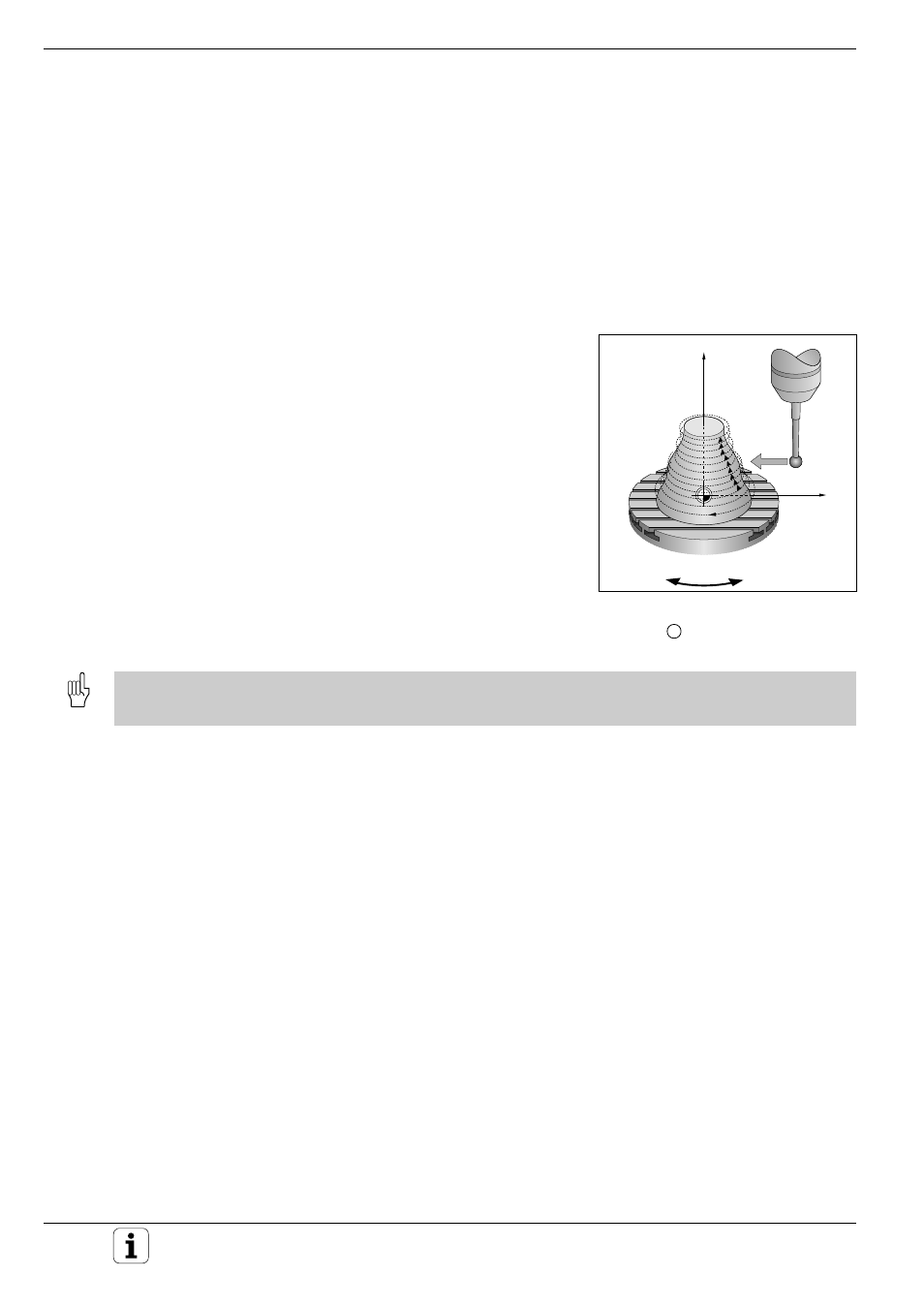
Fig. 9.34:
Line-by-line digitizing with a rotary
axis, line direction C;
1 : L.SPAC
X
Z
C
Digitizing with the TS 120 Touch Probe
Example NC program blocks:
TCH PROBE 5.0
RANGE
TCH PROBE 5.1
PGMNAME: DATRND
TCH PROBE 5.2
Z X+0 A+0 Z+0
TCH PROBE 5.3
X+85 A+270 Z+65
TCH PROBE 5.4 HEIGHT: 50
TCH PROBE 6.0
MEANDER
TCH PROBE 6.1
DIRECTN: A
Defines the A axis as line direction
(see Fig. 9.7)
TCH PROBE 6.2
TRAVEL: 0.3 L.SPAC: 0.5 PP.INT: 0.5
CONTOUR LINES cycle with a rotary axis
Define the starting point in a linear axis and in a rotary axis. Define also
the order and direction of axis approach. If the starting point lies in the X
and C axes, then the touch probe oscillates in the X/C plane.
This method also works well for machines that have only two linear axes
(e.g. Z/X) and one rotary axis (e.g. C).
Example NC program blocks:
TCH PROBE 5.0
RANGE
TCH PROBE 5.1
PGMNAME: DATH
TCH PROBE 5.2
Z X–50 C+0 Z+0
TCH PROBE 5.3
X+50 C+360 Z+85
TCH PROBE
5.4
HEIGHT: 50
TCH PROBE 7.0
CONTOUR LINES
TCH PROBE 7.1
TIME: 250 X+80 C+0
TCH PROBE 7.2
ORDER: X–/C+
TCH PROBE 7.3
TRAVEL 0.3 L.SPAC: –0.5 PP.INT: 0.5
The direction of rotation defined behind ORDER is valid for all levels (lines). This ensures that the workpiece is then
machined consistently either in up-cut or in climb milling.
