HEIDENHAIN TNC 407 (280 580) User Manual User Manual
Page 13
TNC 425/TNC 415 B/TNC 407
1-12
1
Introduction
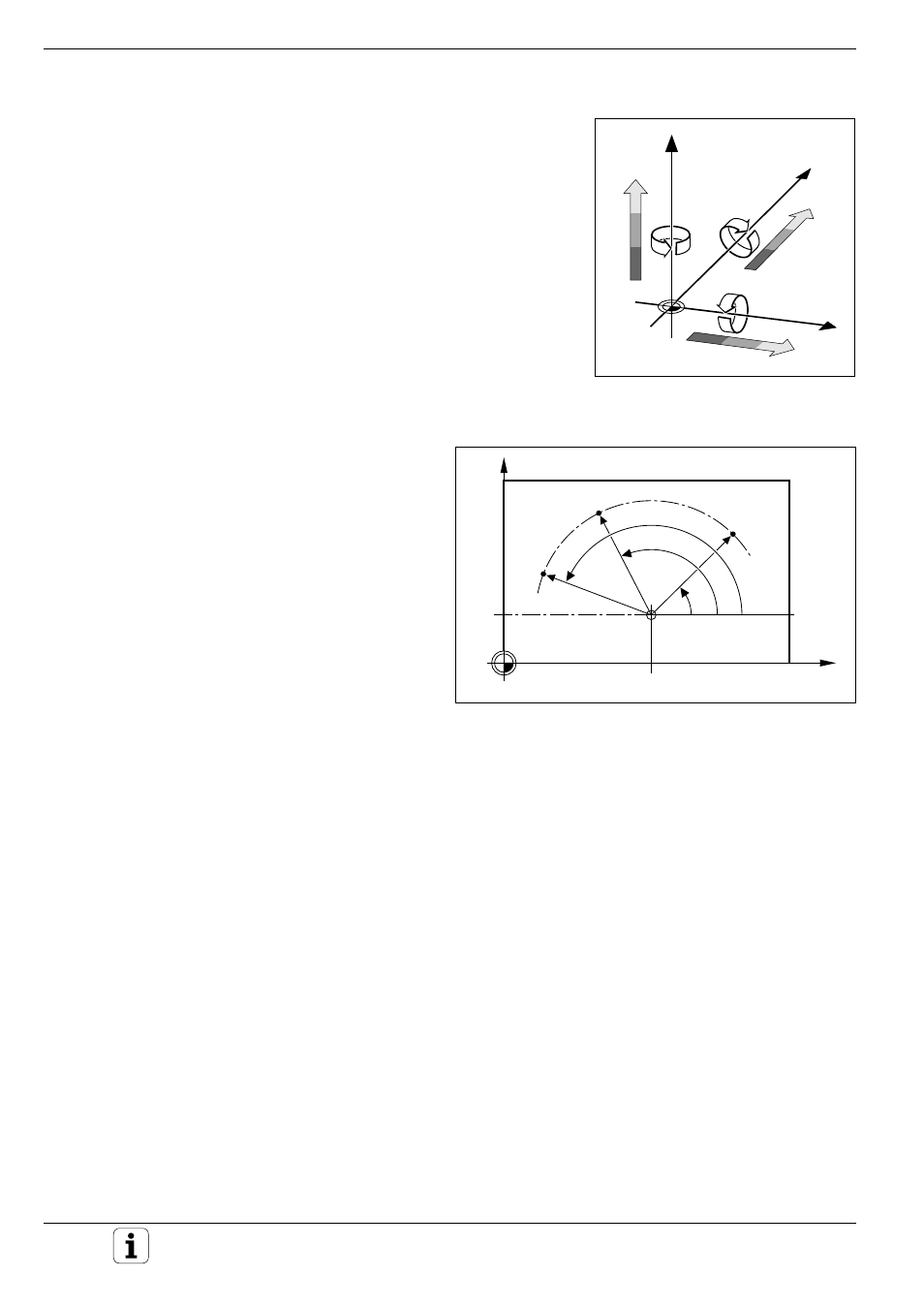
Fig. 1.12:
Identifying positions on a circular arc with polar coordinates
X
Y
10
CC
0
°
30
PA
1
PA
2
PA
3
PR
PR
PR
Fig. 1.11:
Direction and designation of
additional axes
Y
B+
V+
X
Z
C+
A+
W+
U+
Additional axes
The TNCs (except TNC 407) can control the machine in more than three
axis. The axes U, V and W are secondary linear axes parallel to the main
axes X, Y and Z, respectively (see illustration). Rotary axes are also
possible. They are designated as A, B and C.
Polar coordinates
The Cartesian coordinate system is especially
useful for parts whose dimensions are mutually
perpendicular. For parts containing circular arcs or
angles it is often simpler to give the dimensions in
polar coordinates. While Cartesian coordinates are
three-dimensional and can describe points in space,
polar coordinates are two dimensional and describe
points in a plane. Polar coordinates have their
datum at a circle center (CC), or pole, from which a
position is measured in terms of its distance from
that pole and the angle of its position in relation to
the pole.
You could think of polar coordinates as the result of
a measurement using a scale whose zero point is
fixed at the datum and which you can rotate to
different angles in the plane around the pole.
The positions in this plane are defined by
• the Polar Radius (PR) which is the distance
from the circle center CC to the position,
and the
• Polar Angle (PA) which is the size of the
angle between the reference axis and the scale.