HEIDENHAIN TNC 407 (280 580) User Manual User Manual
Page 250
8-43
8
Cycles
TNC 407/TNC 415 B/TNC 425
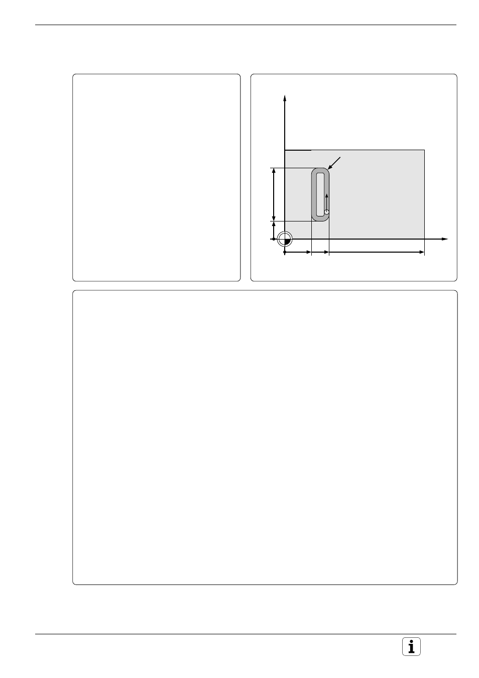
Example:
Rectangular channel on a cylindrical surface
Channel width
20 mm
Channel height
60 mm
Depth
7.5 mm
Cylinder diameter
50 mm
Length of programming plane =
Circumference of the cylinder:
3.14 x 50 mm = 157 mm
Dimensional data for the rotary axis in mm
(Q17 = 1).
Cycle in a part program
0
BEGIN PGM CYLSURF MM
1
TOOL DEF 1 L+0 R+3.5
2
TOOL CALL 1 Y S2000 DL+0.5 .......................... Call the tool, tool axis is Y
3
L Y+200 R0 F MAX
4
CYCL DEF 14.0 CONTOUR GEOM.
5
CYCL DEF 14.1 CONTOUR LABEL 1 ................. Define number of the subprogram for the plane
contour
6
CYCL DEF 27.0 CYLINDER SURFACE ............... Define the cycle CYLINDER SURFACE
Q1=-7.5
;MILLING DEPTH
Q3=+0
;ALLOWANCE FOR SIDE
Q6=+2
;SETUP CLEARANCE
Q10=+4
;PECKING DEPTH
Q11=100
;FEED RATE FOR PECKING
Q12=250
;FEED RATE FOR MILLING
Q16=+25
;RADIUS
Q17=1
;DIMENSION TYPE (ANG/LIN)
7
L C+0 R0 F MAX M3 .......................................... Pre-position the rotary axis
8
CYCL CALL ......................................................... Call the cycle
9
L Y+200 R0 F MAX M2 ...................................... Retract, end of main program
10
LBL 1
11
L C+40 Z+20 RL ................................................. Starting position C 40 mm
12
L C+50 Z+20
13
RND R7.5
14
L IZ+60
15
RND R7.5
16
L IC–20
17
RND R7.5
18
L Z+20
19
RND R7.5
20
L C+40
21
LBL 0 .................................................................. End of subprogram
22
END PGM CYLSURF MM
C
Z
30
60
50
157
20
R7,5