HEIDENHAIN TNC 407 (280 580) User Manual User Manual
Page 203
TNC 425/TNC 415 B/TNC 407
7-18
7
Programming with Q Parameters
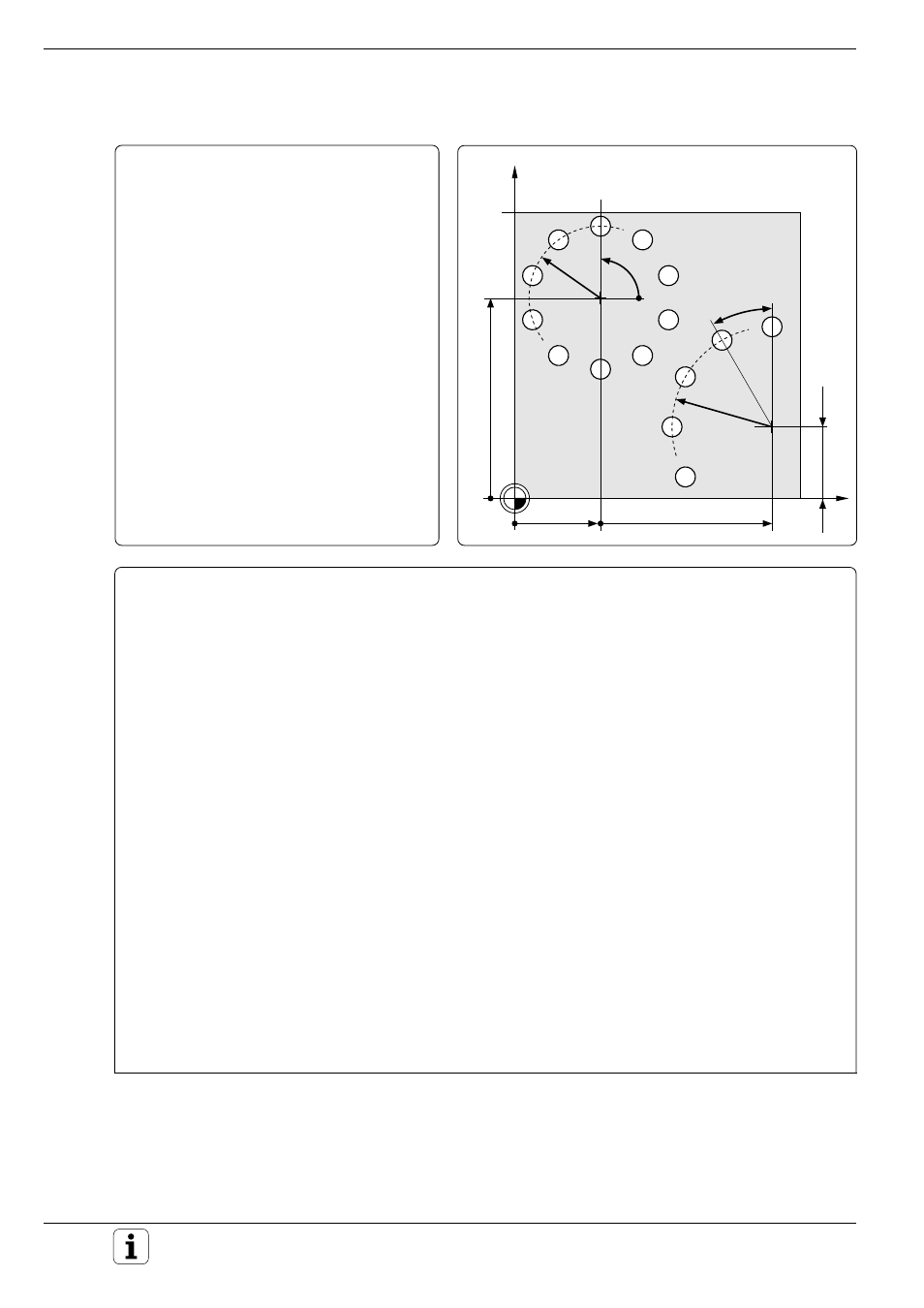
Bolt hole circle
Bore pattern distributed over a full circle:
Entry values are listed below in program
blocks 1 - 8.
Movements in the plane are programmed
with polar coordinates.
Bore pattern distributed over a circle sector:
Entry values are listed below in lines 20 - 24,
Q5, Q7 and Q8 remain the same.
X
Y
30
90
1
2
25
35
25
70
90
°
30
°
Continued ...
Part program
0 BEGIN PGM K71 MM ............................................. Load data for bolt hole circle 1:
1 FN 0: Q1 = + 30 ...................................................... Circle center X coordinate
2 FN 0: Q2 = +70 ....................................................... Circle center Y coordinate
3 FN 0: Q3 = +11 ....................................................... Number of holes
4 FN 0: Q4 = +25 ....................................................... Circle radius
5 FN 0: Q5 = +90 ....................................................... Start angle
6 FN 0: Q6 = +0 ......................................................... Hole angle increment (0: distribute holes over 360°)
7 FN 0: Q7 = +2 ......................................................... Setup clearance
8 FN 0: Q8 = +15 ....................................................... Total hole depth
9 BLK FORM 0.1 Z X+0 Y+0 Z–20
10 BLK FORM 0.2 X+100 Y+100 Z+0
11 TOOL DEF 1 L+0 R+4
12 TOOL CALL 1 Z S2500
13 CYCL DEF 1.0 PECKING ....................................... Definition of the pecking cycle
14 CYCL DEF 1.1 SET UP +Q7 .................................. Setup clearance
15 CYCL DEF 1.2 DEPTH –Q8 ................................... Total hole depth according to the load data
16 CYCL DEF 1.3 PECKG +5
17 CYCL DEF 1.4 DWELL 0
18 CYCL DEF 1.5 F250
19 CALL LBL 1 ........................................................... Call bolt hole circle 1, load data for bolt hole circle 2
(only re-enter changed data):
20 FN 0: Q1 = +90 ..................................................... New circle center X coordinate
21 FN 0: Q2 = +25 ..................................................... New circle center Y coordinate
22 FN 0: Q3 = +5 ....................................................... New number of holes
23 FN 0: Q4 = +35 ..................................................... New circle radius
24 FN 0: Q6 = +30 ..................................................... New hole angle increment (not a full circle, 5
holes at 30° intervals)
25 CALL LBL 1 ........................................................... Call bolt hole circle 2
26 L Z+200 R0 F MAX M2