HEIDENHAIN TNC 407 (280 580) User Manual User Manual
Page 214
8-7
8
Cycles
TNC 407/TNC 415 B/TNC 425
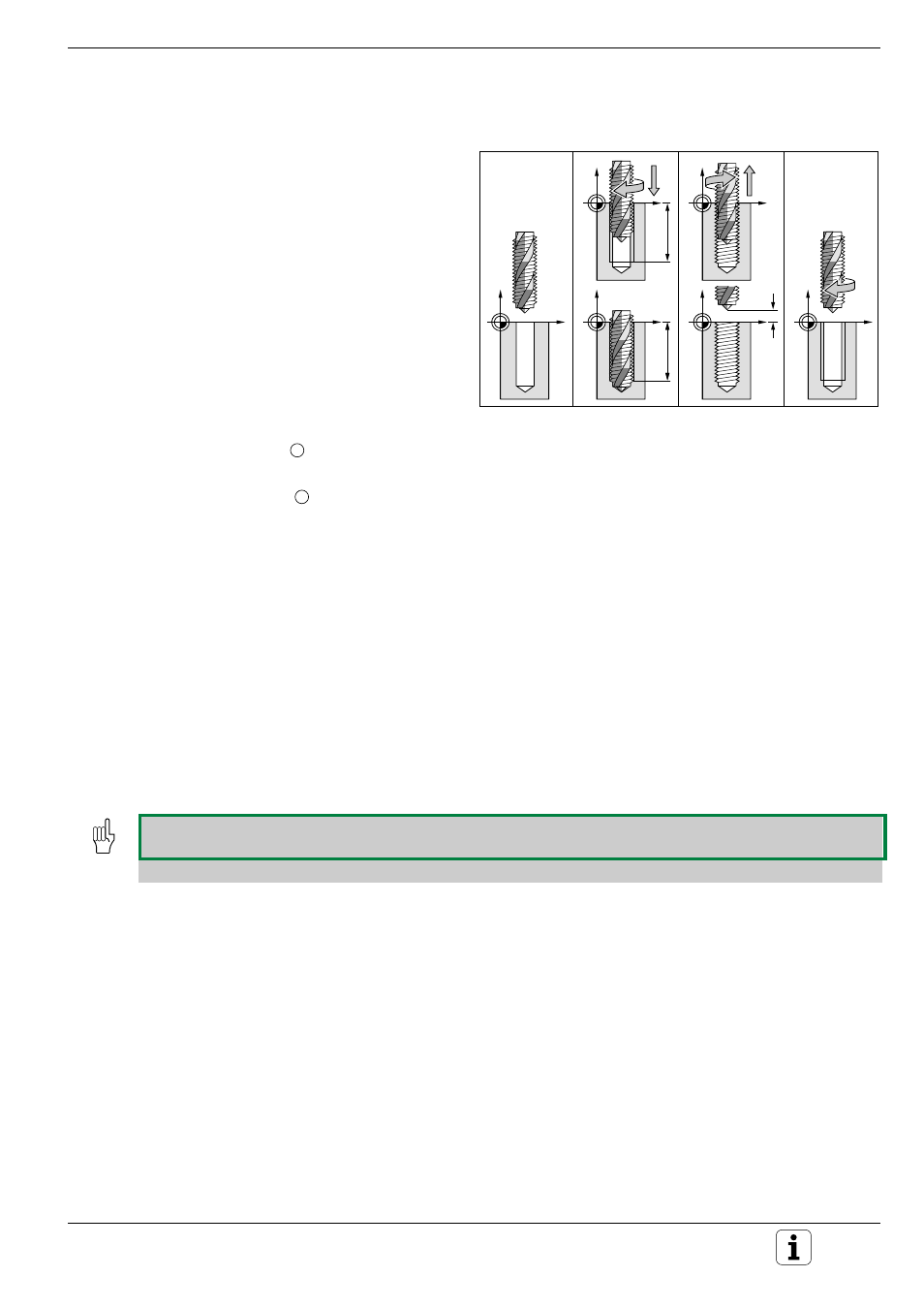
Fig. 8.2: TAPPING cycle
1.
2.
3.
4.
B
B
A
B
TAPPING with floating tap holder (Cycle 2)
Process
• The tread is cut in one pass.
• Once the tool has reached the total hole depth,
the direction of spindle rotation is reversed and
the tool is retracted to the starting position at the
end of the dwell time.
• At the starting position, the direction of spindle
rotation is reversed once again.
Required tool
A floating tap holder is required for tapping. It must
compensate the tolerances between feed rate and
spindle speed during the tapping process.
Input data
• SETUP CLEARANCE
A
:
Distance between tool tip (at starting position) and workpiece surface.
Standard value: approx. 4 x thread pitch
• TOTAL HOLE DEPTH
B
(thread length):
Distance between workpiece surface and end of thread. The algebraic
sign determines the working direction (a negative value means negative
working direction).
• DWELL TIME:
Enter a dwell time between 0 and 0.5 seconds to avoid wedging of the
tool when retracted (further information is available from the machine
manufacturer).
• FEED RATE F:
Traversing speed of the tool during tapping.
Calculations
The feed rate is calculated as follows:
F = S x p
F: Feed rate (mm/min)
S: Spindle speed (rpm)
p: Thread pitch (mm)
• When a cycle is being run, the spindle speed override knob is disabled. The feed rate override knob is only
active within a limited range (preset by the machine manufacturer).
• For tapping right-hand threads activate the spindle with M3, for left-hand threads use M4.