Tch probe 5.0 range, Yx z – HEIDENHAIN TNC 407 (280 580) User Manual User Manual
Page 291
TNC 425/TNC 415 B/TNC 407
9-24
9
3D Touch Probe Systems
Defining the digitizing range
The TM 110 touch probe provides two cycles for defining the digitizing
range. Cycle 5 RANGE defines a cuboid range within which the touch
probe scans the contour. With cycle 15 RANGE (TABLE) you can select a
contour point table in which the shape of the digitizing range is defined
as a polygon.
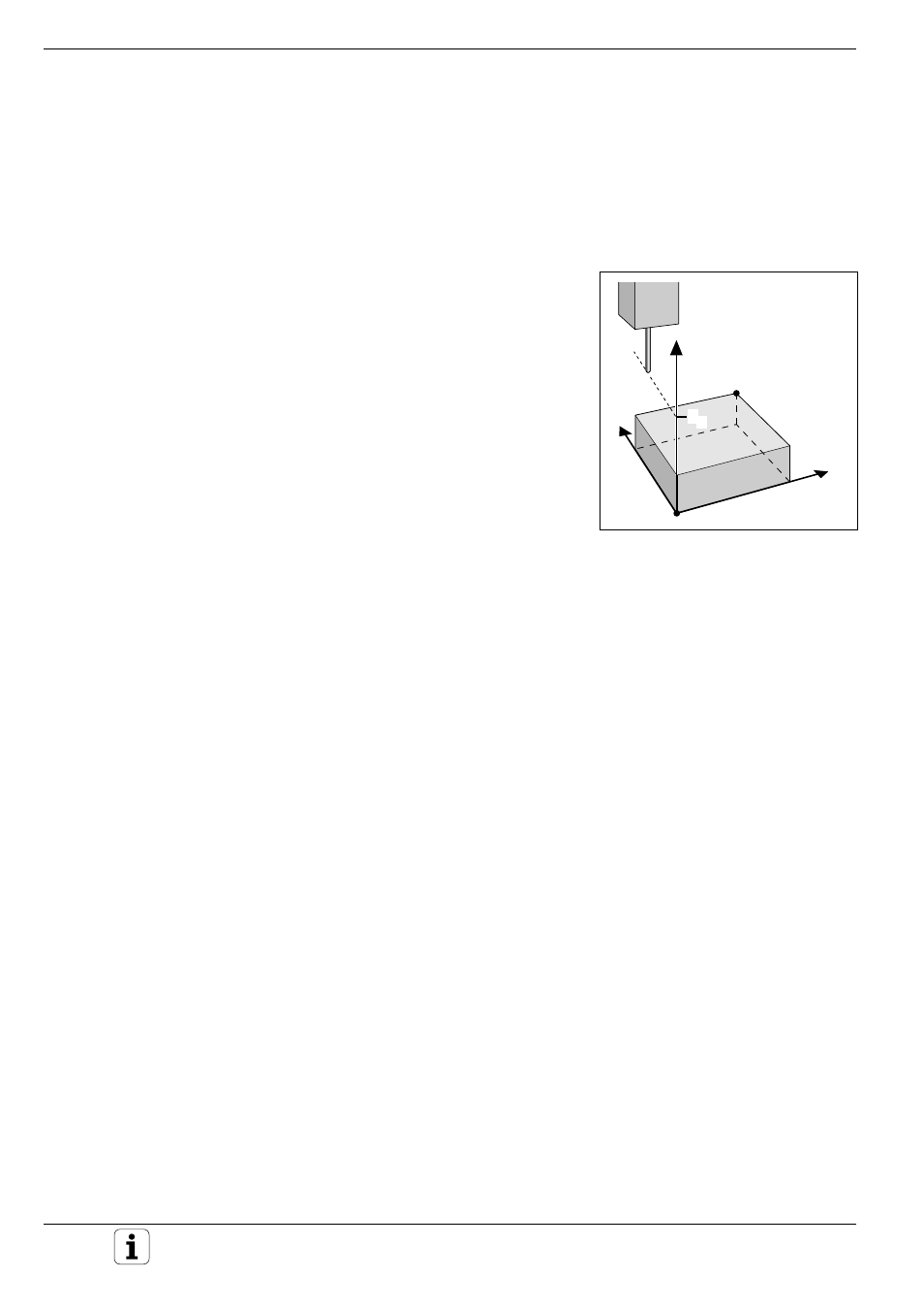
Defining a cuboid digitizing range
The digitizing range is programmed – similar to defining the workpiece
blank – by entering the MIN and MAX point coordinates of the three main
axes X, Y and Z.
Input
• PGM NAME DIGITIZING DATA?
Name of the file in which the digitized data is to be stored
• TCH PROBE AXIS ?
Enter the touch probe axis
• MIN. POINT RANGE
Lowest coordinates in the range to be digitized
• MAX. POINT RANGE
Highest coordinates in the range to be digitized
• CLEARANCE HEIGHT
Position in the probe axis at which the stylus cannot collide with the
model
Fig. 9.20:
Clearance height and cuboid
digitizing range
Digitizing with a Measuring Touch Probe
Y
X
Z
MAX
MIN
S
Z