6 contours – fk free contour programming, Programming contour elements with fk – HEIDENHAIN TNC 407 (280 580) User Manual User Manual
Page 140
5–41
TNC 425/TNC 415 B/TNC 407
5.6
Contours – FK Free Contour Programming
5
Programming Tool Movements
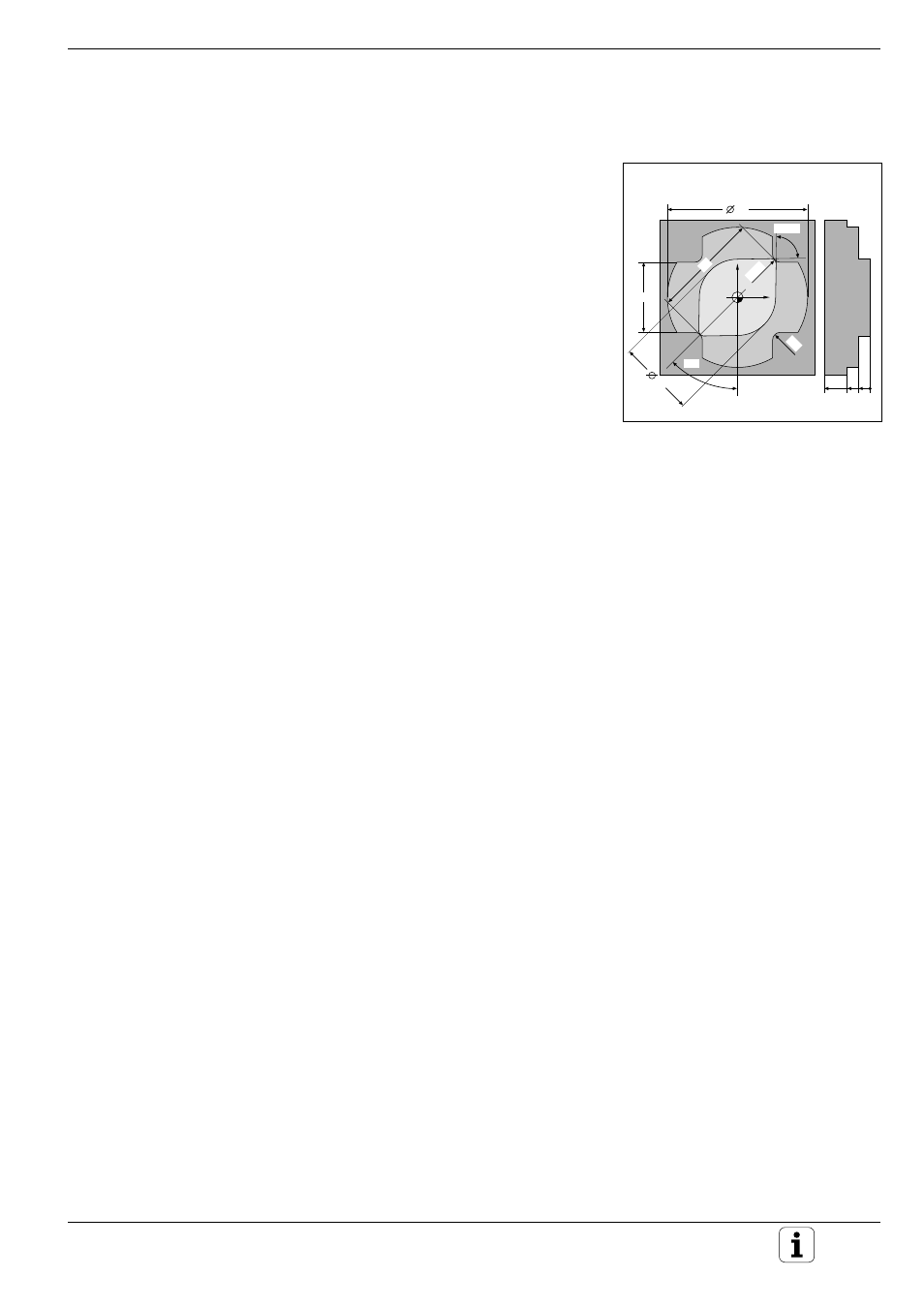
Fig. 5.45:
These dimensions can be
programmed with FK
X
Y
88,15
°
36
21
18
45
°
R4
28
R2,5
40
20 10 0
5.6 Contours – FK Free Contour Programming
Workpiece drawings often contain unconventional coordinate data that
cannot be entered with the gray path function keys. You can enter such
dimensional data directly on the TNC by using its FK free contour program-
ming feature.
FK programming allows you to define a contour element through
• Auxiliary points on the contour element
• Auxiliary points in its proximity
• A reference to another contour element
• Directional data
• Data regarding the course of the contour
FK programming is supported with soft keys.
Programming contour elements with FK
FK contour elements must lie in the working plane perpendicular to the
spindle axis as it was defined in the first BLK FORM of a program.
You must enter all available data for every contour element. Even data that
does not change must be entered in every block – otherwise it is not
recognized.
After you have entered all known data for a contour element, close the
block with END.
If both FK blocks and conventional blocks are entered in a program, the FK
contour must be fully defined before you can return to conventional
programming.
Pre-positioning
You must first pre-position the tool with a gray path function key. The
programmed position must be near a well-defined contour element. If the
coordinates of the first contour point are known, you can pre-position the
tool with the traversing function.