HEIDENHAIN TNC 407 (280 580) User Manual User Manual
Page 271
TNC 425/TNC 415 B/TNC 407
9-4
9
3D Touch Probes
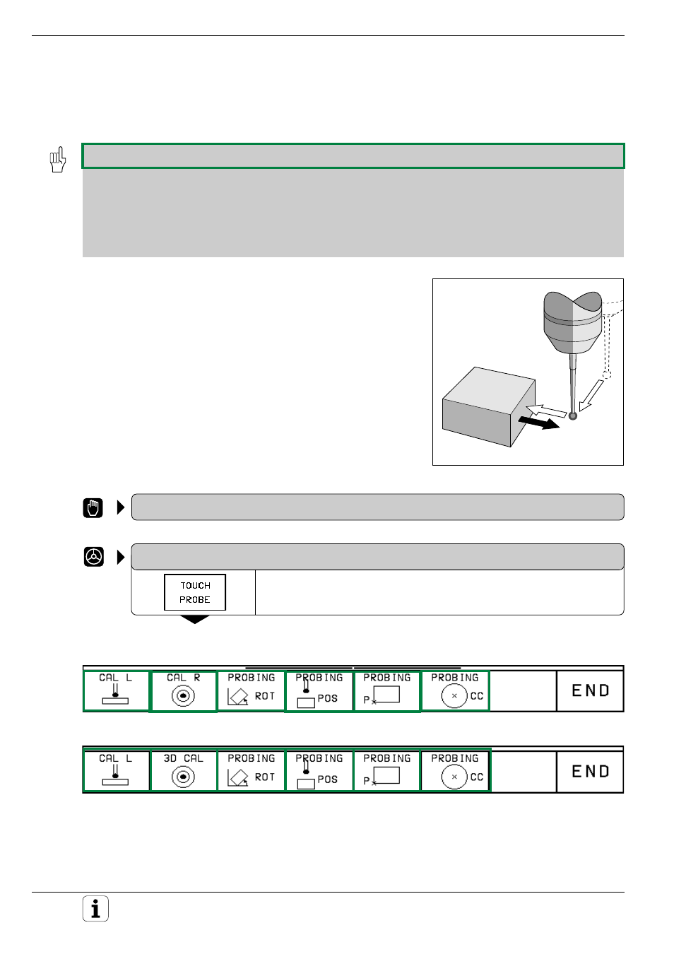
Fig. 9.5:
Feed rates during probing
F
max
F
F
9.2 Touch Probe Cycles in the MANUAL and ELECTRONIC HANDWHEEL
Operating Modes
• The TNC must be specially prepared by the machine manufacturer for the use of a 3D touch probe.
• If measurements are to be carried out during program run, be sure that the tool data (length, radius, axis) either
can be used from the calibrated data or from the last TOOL CALL block (selected with MP7411; see page
12-11).
• If you are working alternately with triggering and measuring test probes, be sure that
– the correct touch probe is selected with MP 6200 (see page 12-4)
– the measuring test probe and the triggering test probe are never connected to the control at the same time.
The TNC cannot tell which probe is actually in the spindle.
After you press the machine START button, the touch probe begins
executing the selected probe function. The machine manufacturer sets
the feed rate F at which the probe approaches the workpiece in machine
parameters. When the 3D touch probe contacts the workpiece, it
• transmits a signal to the TNC:
the coordinates of the probed position are stored
• stops moving
• returns to its starting position at rapid traverse.
If the stylus is not deflected within the distance defined in MP6130 (TS
120/TS 511) or MP6330 (TM 110), the TNC displays an error message.
To select the touch probe functions:
MANUAL OPERATION
or
ELECTRONIC HANDWHEEL
Select the touch probe functions.
If you are working with the TS 120 or TS 511 touch probe systems, the
following soft key row will appear on the TNC screen:
With the measuring touch probe, this soft key row will appear: