Tch probe 15.0 range (table) – HEIDENHAIN TNC 407 (280 580) User Manual User Manual
Page 293
TNC 425/TNC 415 B/TNC 407
9-26
9
3D Touch Probe Systems
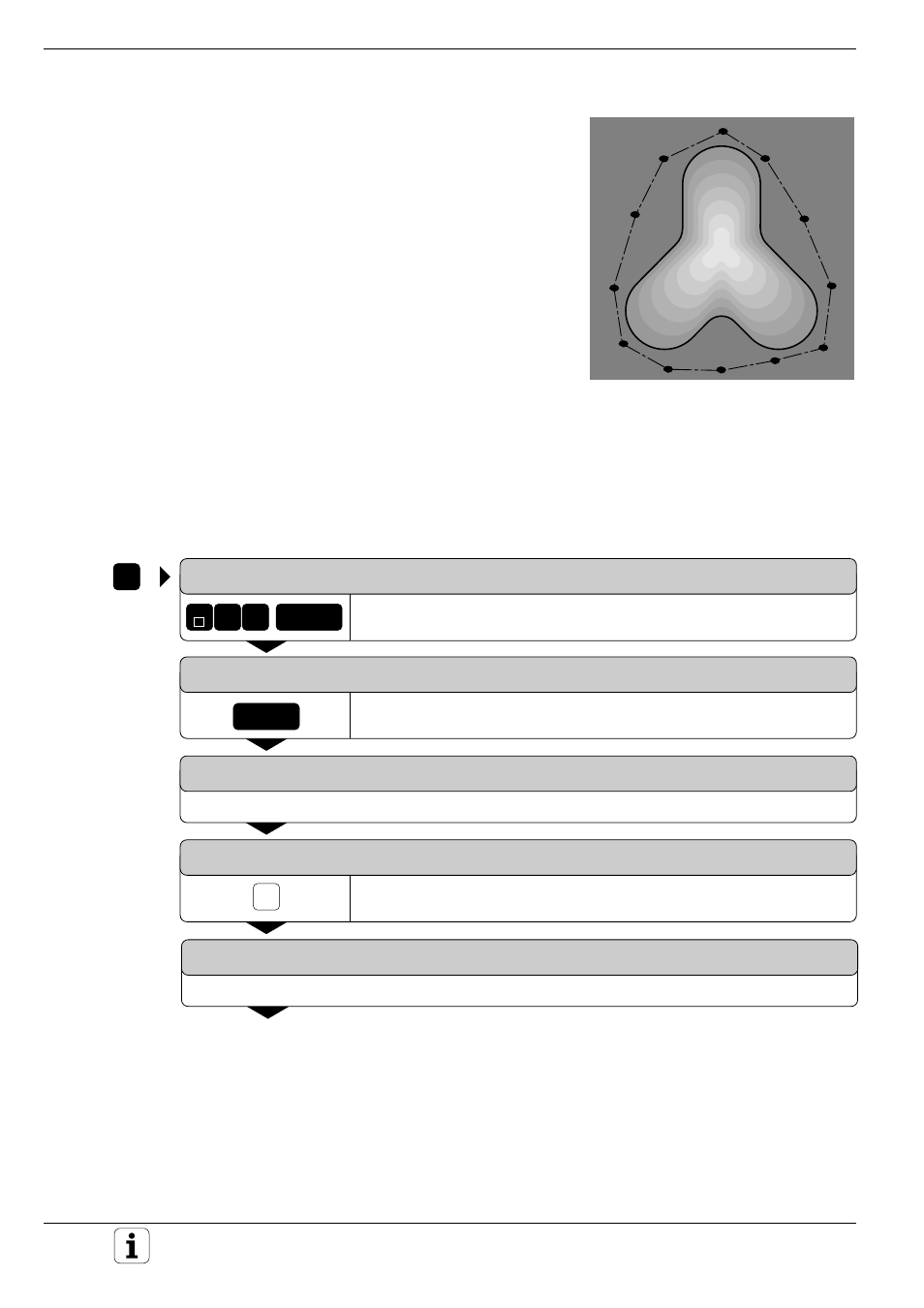
Fig. 9.21:
Defining the digitizing range
by connecting contour points
TOUCH
PROBE
GOTO
5
ENT
Z
ENT
e.g.
1
.
.
.
Digitizing with a Measuring Touch Probe
Defining the digitizing range in a specific shape
The digitizing range is defined by a contour point table generated in the
POSITIONING WITH MDI mode of operation (see page 5-75). You can
either transfer the individual points by teach-in programming or move the
touch probe around the model manually and have the TNC generate
them automatically.
Input
• PGM NAME DIGITIZING DATA ?
Name of the file in which the digitized data is to be stored
• TCH PROBE AXIS ?
Enter the touch probe axis
• PGM NAME RANGE DATA ?
Enter the name of the point table in which you have defined the range
• MIN. POINT TCH PROBE AXIS ?
Lowest probe axis coordinate in the DIGITIZING range
• MAX. POINT TCH PROBE AXIS ?
Highest probe axis coordinate in the DIGITIZING range
• CLEARANCE HEIGHT ?
Position in the probe axis at which the stylus cannot collide with the
model
To program TCH PROBE 15.0:
TCH PROBE: 0 REF. PLANE
Select digitizing cycle 15 RANGE (TABLE).
TCH PROBE: 15 RANGE (TABLE)
Confirm your selection.
PGM NAME DIGITIZING DATA?
Enter the name of the file in which the digitizing data should be stored.
TCH PROBE AXIS?
Enter the touch probe axis.
PGM NAME RANGE DATA ?
Enter the name of the contour point table in which the range is defined.