Yx z, Helical interpolation – HEIDENHAIN TNC 407 (280 580) User Manual User Manual
Page 137

TNC 425/TNC 415 B/TNC 407
5-38
5
Programming Tool Movements
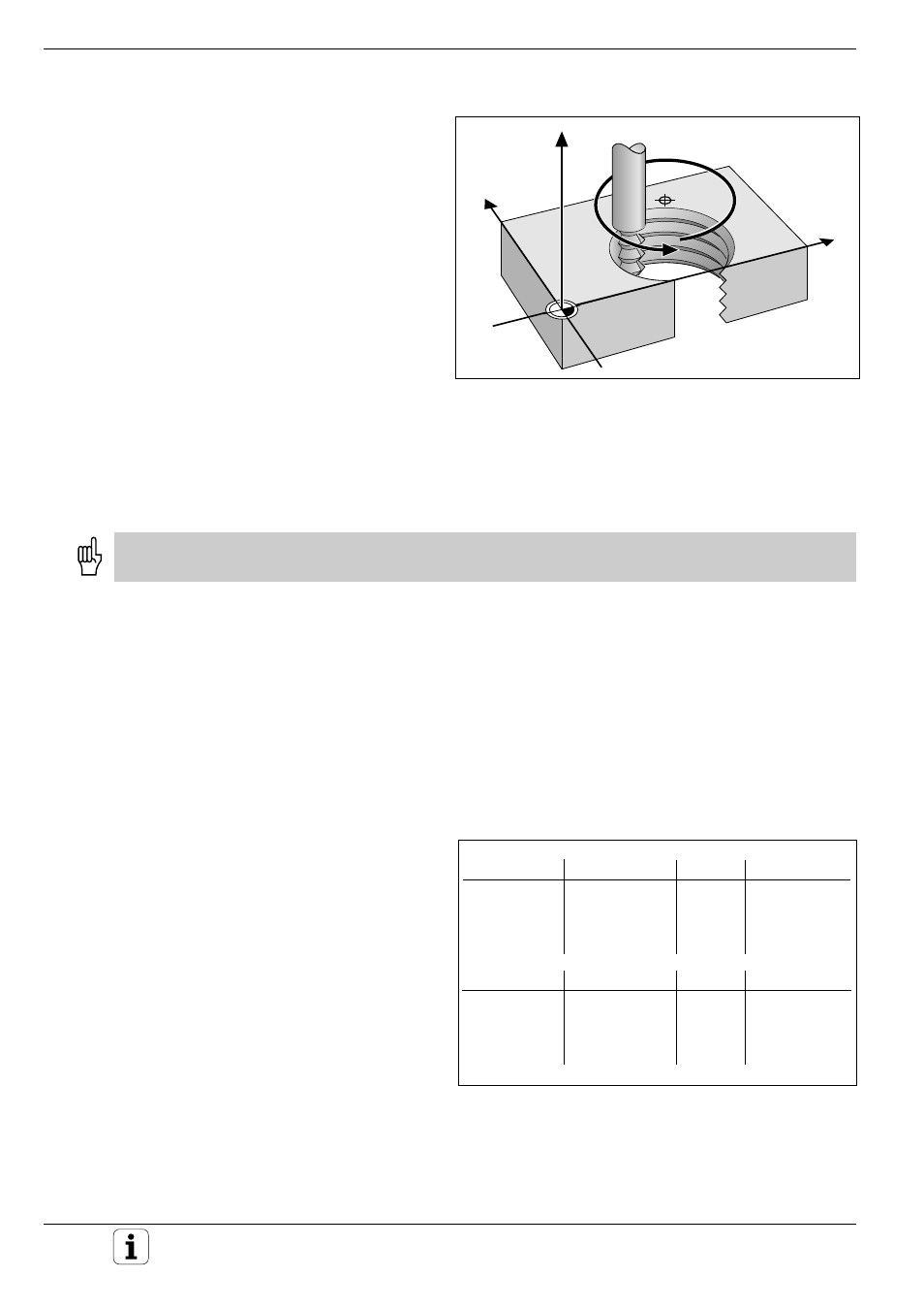
Fig. 5. 43: Helix: a combination of circular and linear paths
Y
X
Z
CC
Path Contours - Polar Coordinates
Helical interpolation
A helix is a combination of a circular movement in
a main plane and a linear movement perpendicular
to this plane.
A helix is programmed only in polar coordinates.
Applications:
You can use helical interpolation with form cutters
to machine:
• Large-diameter internal and external threads
• Lubrication grooves
Input
• Total incremental angle of tool traverse on the helix
• Total height of the helix
Input angle
Always enter the same sign for the rotation as for the incremental input angle. Otherwise the TNC may move the
tool along the wrong path.
Calculate the incremental polar coordinate angle IPA as follows:
IPA = n
.
360°; where
n = number of revolutions of the helical path.
For IPA you can enter any value from –5400° to +5400° (n = 15). If your
thread has more than 15 revolutions, program the helical interpolation in a
program section repeat (see page 5-40).
Input height
Enter the helix height H in the tool axis. The height is calculated as:
H = n x P,
n = number of thread revolutions
P = thread pitch
Radius compensation
Enter the radius compensation for the helix
according to the table at right.
External thread
Right-hand
Left-hand
Right-hand
Left-hand
Work direction
Z+
Z+
Z-
Z-
Direction
DR+
DR-
DR-
DR+
Radius comp.
RR
RL
RL
RR
Internal thread
Right-hand
Left-hand
Right-hand
Left-hand
Work direction
Z+
Z+
Z-
Z-
Direction
DR+
DR-
DR-
DR+
Radius comp.
RL
RR
RR
RL
Fig. 5.44:
The shape of the helix determines the direction of rotation
and the radius compensation
