Approaching the contour – HEIDENHAIN TNC 407 (280 580) User Manual User Manual
Page 105
TNC 425/TNC 415 B/TNC 407
5-6
5
Programming Tool Movements
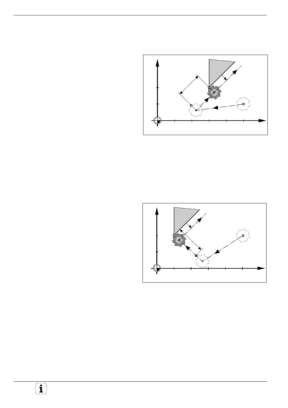
Fig. 5.7:
Approaching on a straight line perpendicular to the first
contour point
Contour Approach and Departure
Fig. 5.6:
Approaching on a straight line with tangential connection
Y
X
10
20
30
40
50
10
20
P
A
RR
P
S
RO
LEN
P
H
RR
RR
Y
X
10
20
30
40
50
10
20
P
A
RR
RR
P
S
RO
P
H
RR
LEN
Approaching the contour
Approaching on a straight line with tangential connection: APPR LT
The tool moves on a straight line from the starting
position P
S
to an auxiliary position P
H
located on the
extension of the first contour element. It then
moves from P
H
to the first contour point P
A
. P
H
is
separated from P
A
by the distance LEN.
Input
• Coordinates of the first contour point P
A
• Distance LEN from the auxiliary point P
H
to the
first contour point P
A
• Tool radius compensation for machining
NC blocks
L X+50 Y+10 R0 FMAX M3 ................................ P
S
without radius compensation, rapid traverse, spindle ON with
............................................................................
clockwise rotation
APPR LT X+30 Y+20 Z–10 LEN 15 RR F100 ...... P
A
with radius compensation RR, machining feed rate,
............................................................................
P
H
at distance LEN=15 mm from P
A
L .......................................................................... End point of the 1st contour element
Approaching on a straight line vertical to the first contour point: APPR LN
The tool moves in a straight line from the starting
position P
S
to an auxiliary point P
H
. From P
H
it
moves to P
A
following a path that is perpendicular
to the first contour element. P
H
is separated from
P
A
by the distance LEN.
Input
• Coordinates of the first contour point P
A
• Distance LEN from the auxiliary point P
H
to the
first contour point P
A
• Tool radius compensation for machining
Algebraic sign
Always enter LEN as a positive value.
NC blocks
L X+50 Y+20 R0 FMAX M3 ................................ P
S
without radius compensation, rapid traverse, spindle ON with
clockwise rotation
APPR LN X+10 Y+20 Z–10 LEN+20 RR F100 .... P
A
with radius compensation RR, machining feed rate, P
H
at distance
LEN=20 mm from P
A
L .......................................................................... End point of the 1st contour element