HEIDENHAIN TNC 407 (280 580) User Manual User Manual
Page 23
TNC 425/TNC 415 B/TNC 407
1-22
1
Introduction
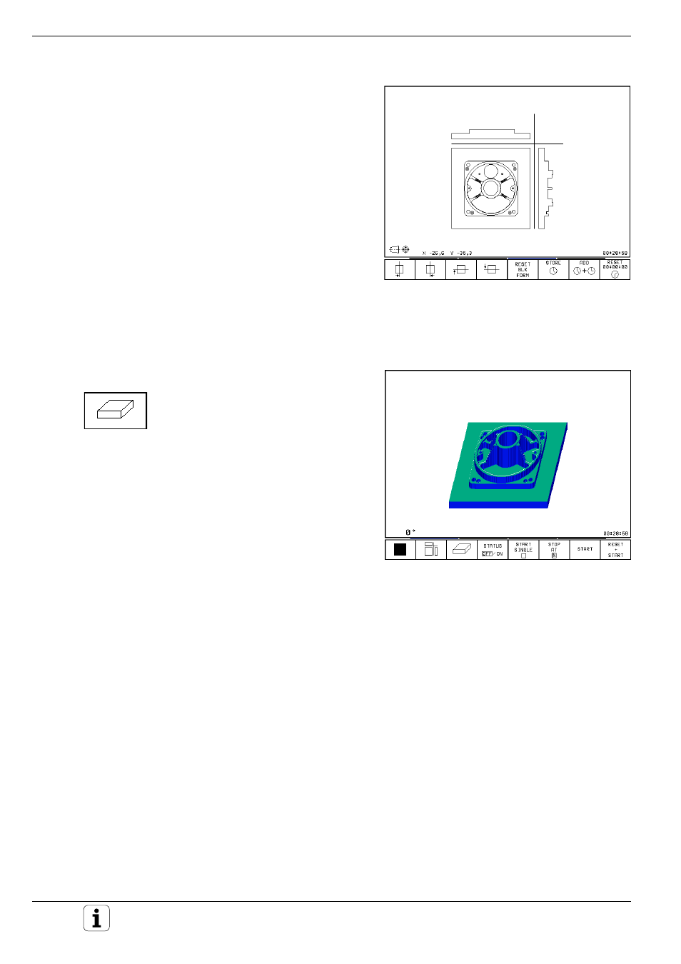
Fig. 1.27:
The coordinates of the cursor position are
displayed to the lower left of the graphic
Fig. 1.28:
TNC graphics, 3D view
Cursor position during projection in 3 planes
The TNC shows the coordinates of the cursor
position at the bottom of the graphics window.
Only the coordinates of the working plane are
shown.
This function is activated with machine parameter
MP7310.
Cursor position during detail magnification
During detail magnification, the TNC displays the
coordinates of the axis that is currently being
moved.
The coordinates describe the area determined for
magnification. To the left of the slash is the small-
est coordinate of the detail in the current axis, to
the right is the largest.
3D view
The workpiece is displayed in three dimensions,
and can be rotated around the vertical axis.
The shape of the workpiece blank can be depicted
by a frame overlay at the beginning of the graphic
simulation.
In the TEST RUN mode of operation you can isolate
details for magnification.