2 contour approach and departure, Positioning for contour approach and departure – HEIDENHAIN TNC 407 (280 580) User Manual User Manual
Page 103
TNC 425/TNC 415 B/TNC 407
5-4
5
Programming Tool Movements
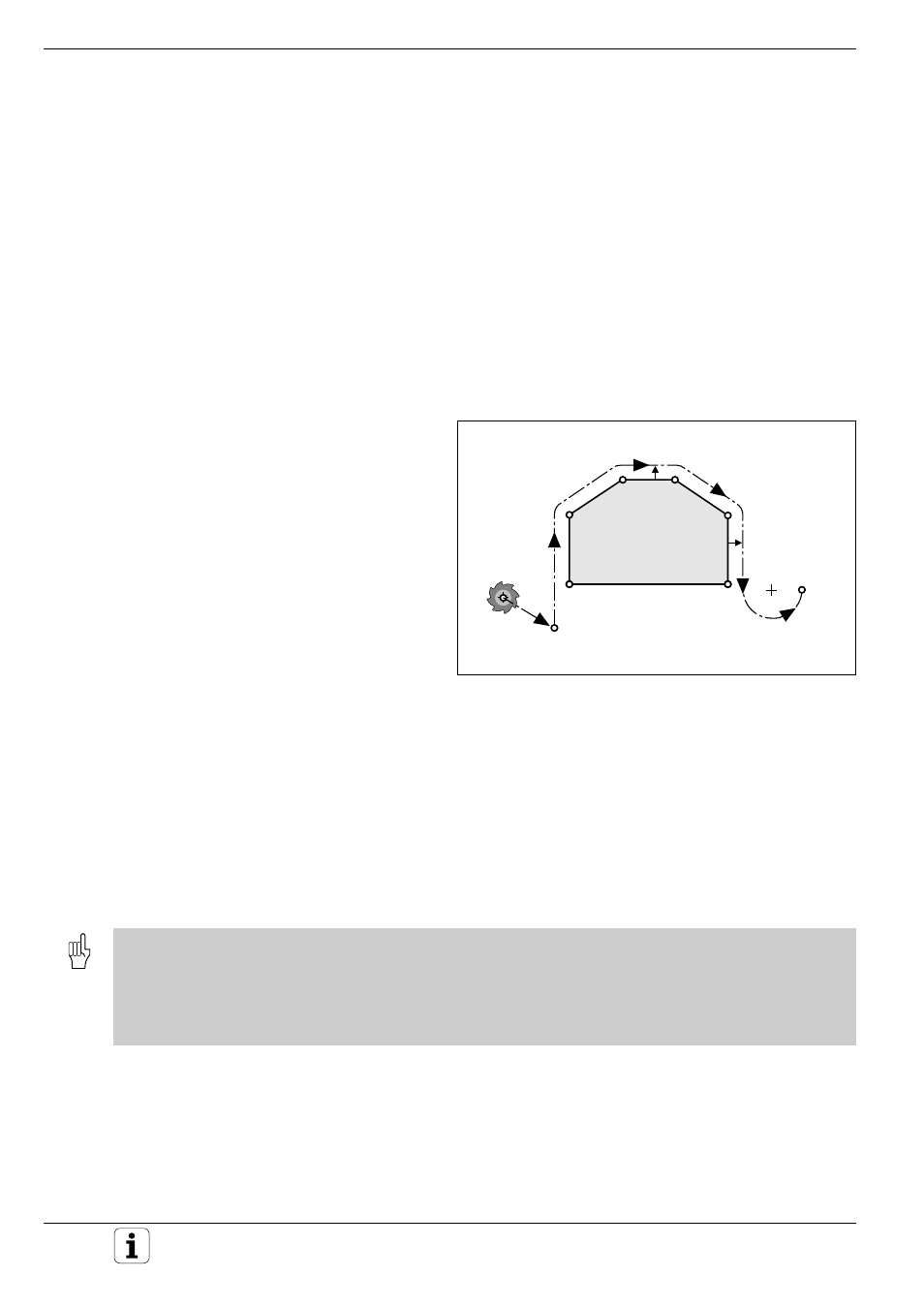
Fig. 5.4:
Points that define contour approach and departure
P
H
RL
P
S
R0
P
A
RL
P
E
RL
P
N
R0
RL
RL
5.2 Contour Approach and Departure
The APPR and DEP functions simplify contour approach and departure.
You can select one of the following types of traverse:
• Straight line, perpendicular or tangential to the contour element
• Circular arc, tangential to the contour element
• Straight line with tangential arc during contour approach
• Circular arc with tangentially departing straight line
Approaching and departing a helix
An especially convenient way to approach and depart a helix is on a
tangential arc. In this way the tool approaches and departs the helix on its
extension.
Positioning for contour approach and departure
The following points are important for contour
approach and departure:
• Starting position P
S
The starting position is programmed in the block
before the contour approach block. It is pro-
grammed without radius compensation (R0) and
lies outside the contour.
• Auxiliary point P
H
Some of the paths for approach and departure
go through an auxiliary point that the TNC
automatically calculates from your input in the
APPR or DEP block.
• First contour point P
A
and last contour point P
E
The first contour point P
A
is programmed in the
APPR block. The last contour point is pro-
grammed as usual. If all three coordinates X, Y
and Z are programmed in the APPR block, the
TNC will first move the tool to the working plane
at P
H
and then move it to the entered depth in
the tool axis. The first contour point can also be
programmed in polar coordinates by pressing the
orange P key after selecting the approach
function.
• End position P
N
The end position P
N
results from the data in the
DEP block and lies outside of the contour.
• The control does not check whether the programmed contour will be damaged when moving from the actual
position to auxiliary point P
H
. Use the test graphics to check for danger of workpiece damage during approach or
departure.
• The TNC moves the tool from the actual position to auxiliary point P
H
at rapid traverse (exception: LCT).
• When approaching the contour, allow sufficient distance between the starting point and the first contour point to
assure that the TNC will reach the programmed feed rate for machining.