Cycl call – HEIDENHAIN TNC 407 (280 580) User Manual User Manual
Page 210
8-3
8
Cycles
TNC 407/TNC 415 B/TNC 425
CYCL
CALL
ENT
3
e.g.
e.g.
e.g.
ENT
e.g.
ENT
0
3
+/
0
.
7
5
ENT
2
.
.
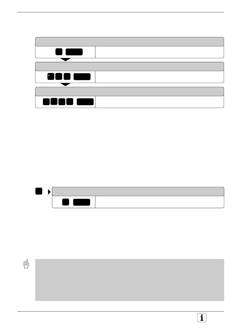
The data for the selected cycle is interrogated by the control:
SETUP CLEARANCE?
Enter setup clearance, e.g. +2 mm.
TOTAL HOLE DEPTH?
Enter total hole depth, e.g. –30 mm.
THREAD PITCH?
Enter thread pitch, e.g. +0.75 mm.
Resulting NC block
17.0
RIGID TAPPING
17.1
SET UP +2
17.2
DEPTH –30
17.3
PITCH +0.75
Cycle call
The following cycles become effective automatically by being defined in
the part program:
• coordinate transformation cycles,
• the dwell time cycle, and
• the SL cycles which determine the contour and the global parameters.
The remaining cycles must be called-up separately. Further information on
cycle call is provided in the descriptions of the individual cycles.
If the cycle is to be executed after the block in which it was called-up,
program the cycle call
• with CYCL CALL
MISCELLANEOUS FUNCTION
Cycle call with miscellaneous function M3.
• with miscellaneous function M99.
If the cycle is to be executed after every positioning block, the cycle must
be called-up with miscellaneous function M89 (depending on machine
parameter MP7440).
The effect of M89 is cancelled with
• M99
• CYCL CALL
• CYCL DEF.
Prerequisites:
The following data must be programmed before a cycle call :
• BLK FORM for graphic display
• Tool call
• Positioning block for starting position X, Y (machining level) with radius compensation R0
• Positioning block for starting position Z (tool axis, safety distance)
• Direction of rotation of the spindle (additional functions M3/M4; exception: cycle 18)
• Cycle definition (CYCLE DEF).