Lenze Engineer v2.21 User Manual
Page 62
Mapping the system structure in the »Engineer« project
Inserting components
62
Lenze · Engineer · 2.13 EN - 10/2014
_ _ _ _ _ _ _ _ _ _ _ _ _ _ _ _ _ _ _ _ _ _ _ _ _ _ _ _ _ _ _ _ _ _ _ _ _ _ _ _ _ _ _ _ _ _ _ _ _ _ _ _ _ _ _ _ _ _ _ _ _ _ _ _
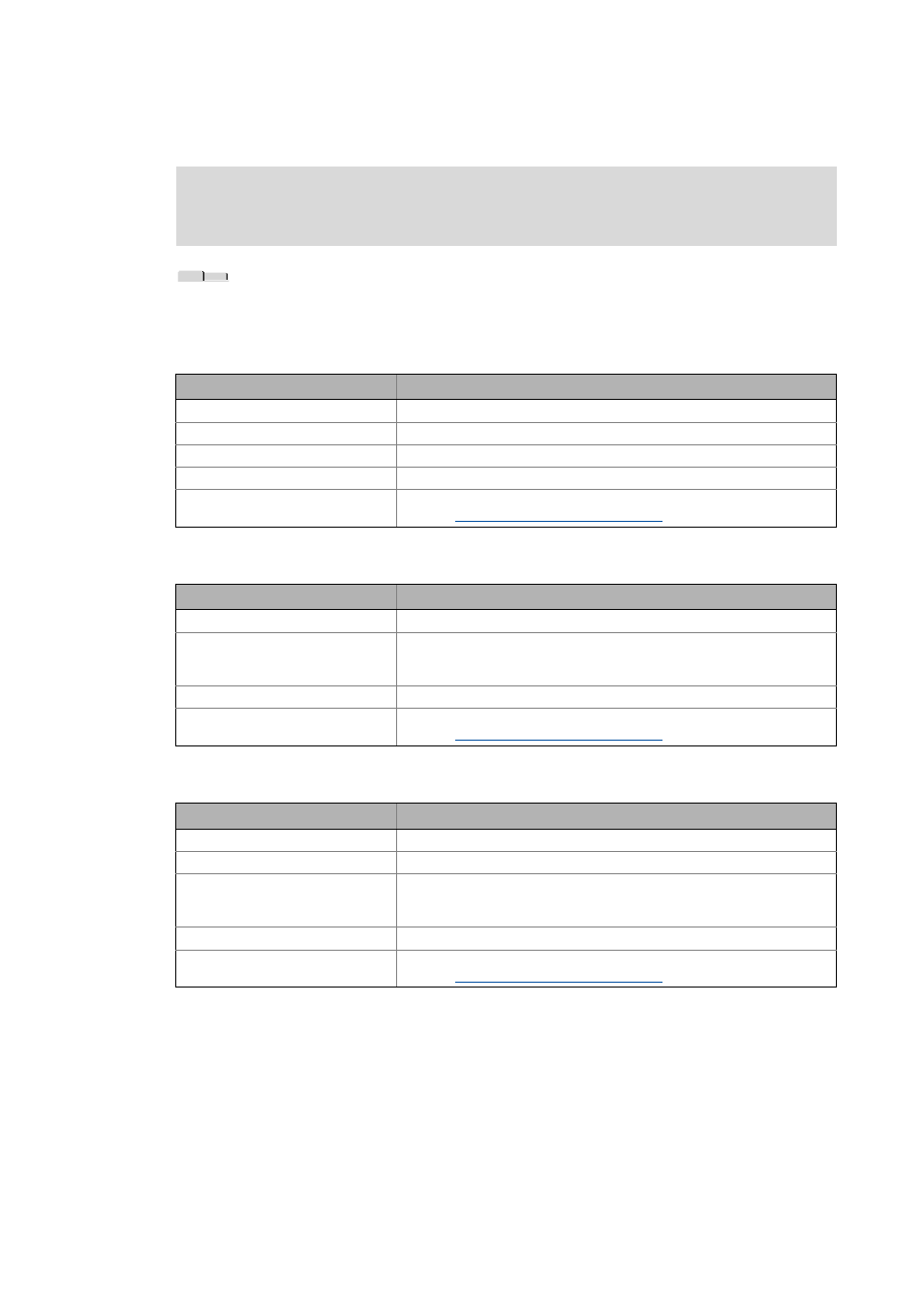
Tabs of the I/O systems
If you select an I/O module in the Project tree, the Workspace contains different tabs.
CAN gateway
CAN gateway module
Compact modules
Note!
Depending on the inserted I/O module, different tabs are available!
Tab
Contents
Configuration
Represents the I/O system.
Ports
Represents the input and output ports of the CAN gateway.
All parameters
Parameters (codes) of the I/O system.
Product features
Project / catalogue information about the I/O system.
Documentation
Optionally, notes regarding the device module and file attachments can be
added.
Documentation - Add project details ( 71)
Tab
Contents
Status
Status of the inputs / outputs.
Parameter
Parameters (codes) of the I/O system.
• The parameters of the digital modules, for instance, define how the
control signals must be transmitted (original / inverted polarity).
Product features
Project / catalogue information about the I/O system.
Documentation
Optionally, notes regarding the device module and file attachments can be
added.
Documentation - Add project details ( 71)
Tab
Function
Configuration
Represents the I/O system.
Ports
Represents the input / output ports of the I/O module.
All parameters
Parameters (codes) of the I/O system.
• The parameters of the digital modules, for instance, define how the
control signals must be transmitted (original / inverted polarity).
Product features
Project / catalogue information about the I/O system.
Documentation
Optionally, notes regarding the device module and file attachments can be
added.