Lenze Engineer v2.21 User Manual
Page 45
Lenze · Engineer · 2.13 EN - 10/2014
45
Mapping the system structure in the »Engineer« project
_ _ _ _ _ _ _ _ _ _ _ _ _ _ _ _ _ _ _ _ _ _ _ _ _ _ _ _ _ _ _ _ _ _ _ _ _ _ _ _ _ _ _ _ _ _ _ _ _ _ _ _ _ _ _ _ _ _ _ _ _ _ _ _
5
Mapping the system structure in the »Engineer« project
The »Engineer« provides for a cross-device parameterisation, configuration, and diagnostics of
individual components and machine control systems. For this, map the system structure of your
automation system in the »Engineer«.
Getting started
In the project tree/device tree, you create the hierarchical project structure that usually results from
the following components:
• ... the functional division of the whole system into different partial systems/modules
(e.g. conveyor and press) as well as from
• ... components of the automation system (e.g. inverters, control systems, motors).
Tip!
On the basis of your system you can represent this structure 1:1 in the »Engineer« project.
You can modularise the structure of the machine system with several system modules/
axes.
General procedure
Representing the real system structure in the project tree
From here you can add items to the system structure by inserting other system modules and/or
axes: Right-click
the desired project elementInsert system module/Insert axis
Extending the system structure
Step
Activity
1st
Modularising with system modules and axes ( 47)
2nd
3rd
4th
Documentation - Add project details ( 71)
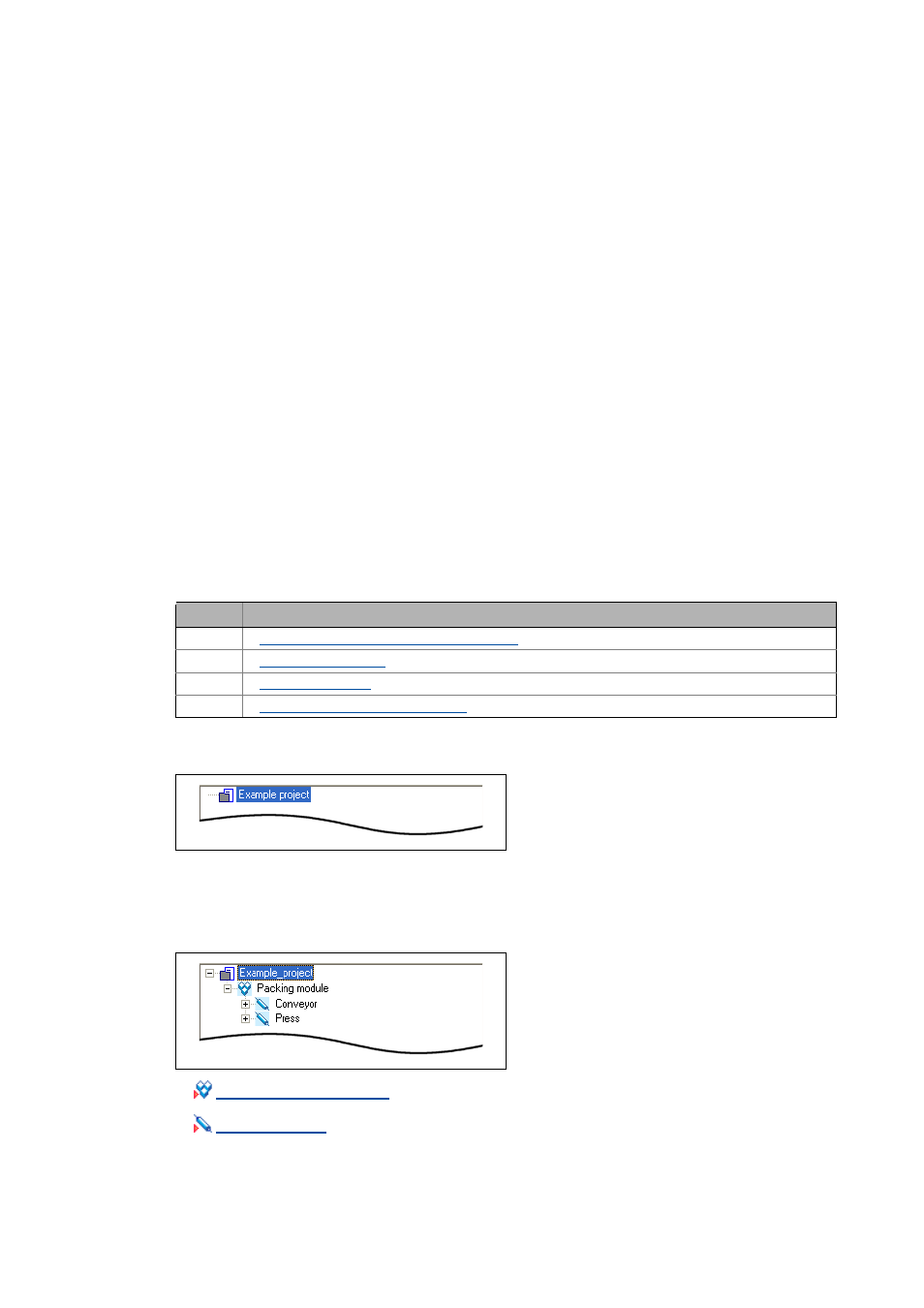
• If you create a new (empty) project, all that
can be seen at first in the Project tree is the
Project root including the project name.
• In our example project, the projected
system includes a Packing module system
module.
• The packing module is divided into two
axes: Conveyor and Press.