1 user interface, Appendix – Lenze Engineer v2.21 User Manual
Page 280
Appendix
Creating cam data with the »Cam Editor«
280
Lenze · Engineer · 2.13 EN - 10/2014
_ _ _ _ _ _ _ _ _ _ _ _ _ _ _ _ _ _ _ _ _ _ _ _ _ _ _ _ _ _ _ _ _ _ _ _ _ _ _ _ _ _ _ _ _ _ _ _ _ _ _ _ _ _ _ _ _ _ _ _ _ _ _ _
14.3.1
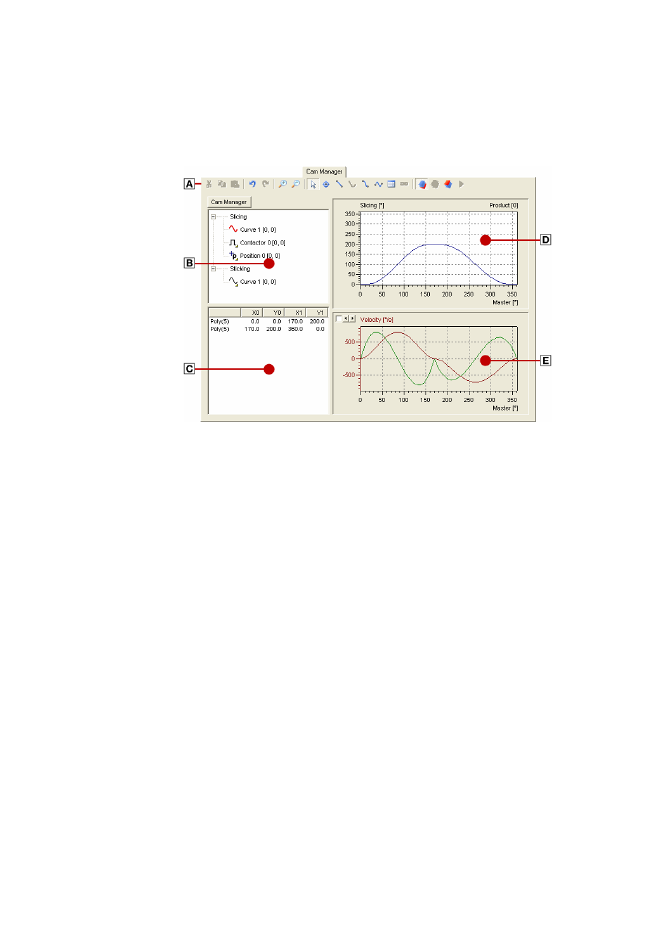
User interface
A change from the »Cam Manager« to the »Cam Editor« results in the latter being displayed in the
Cam Manager tab:
A. Using the icons in the »Cam Editor« Toolbar is the simplest way to execute some of the most
frequently used menu commands of the »Cam Editor«, omitting the need to click the Menu bar
first.
B. In the Project tree, the existing tracks are shown.
• The Project tree is necessary in addition to the known »Engineer« Project view because not all
drives of an electrical shaft have to have a cam function.
C. The Object list is a list of all objects in active mode.
• Each line in the list contains the object type and the coordinates of the object.
• The lines are sorted according to the X values (master). This is a standard setting. A different
sorting sequence can be achieved by clicking the fields in the header.
D. The Worksheet is the drawing area for entering and editing graphic objects for the track selected
in the Project tree.
E. Under the Worksheet, the Time derivations of the objects (speed, acceleration and jerk) are
shown.