Defining the system functionality – Lenze Engineer v2.21 User Manual
Page 197
Lenze · Engineer · 2.13 EN - 10/2014
197
Defining the system functionality
Creating an interconnection via the electrical shaft
_ _ _ _ _ _ _ _ _ _ _ _ _ _ _ _ _ _ _ _ _ _ _ _ _ _ _ _ _ _ _ _ _ _ _ _ _ _ _ _ _ _ _ _ _ _ _ _ _ _ _ _ _ _ _ _ _ _ _ _ _ _ _ _
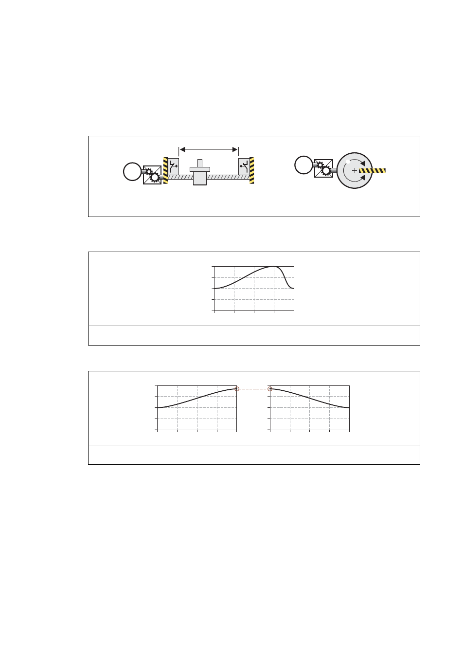
Limited traversing range
• The traversing range is limited by positive and negative position limits (mechanical limits/travel
range limit switches/software limit positions).
• After a defined distance, traversing must take place in the opposite direction again (example:
spindle drive/linear axis).
[8-18] Examples of a limited traversing range
• Typical curves for the limited traversing range:
[8-19] Example 1: Closed curve trace (forward-back profile)
[8-20] Example 2: Closed curve trace (forward-back profile) as a sequence by means of two machine cycles ("weaving loom"
principle)
Traversing range
Mechanical limit (limit stop)
M
M
Y = position of the axis
X = master value/master angle
0
50
100
-50
-100
Y [mm]
90º
180º
270º
360º
0º
j
Y = position of the axis
X = master value/master angle
0
50
100
-50
-100
Y [mm]
90º
180º
270º
360º
0º
j
0
50
100
-50
-100
Y [mm]
90º
180º
270º
360º
0º
j