Defining the system functionality – Lenze Engineer v2.21 User Manual
Page 183
Lenze · Engineer · 2.13 EN - 10/2014
183
Defining the system functionality
Creating an interconnection via the electrical shaft
_ _ _ _ _ _ _ _ _ _ _ _ _ _ _ _ _ _ _ _ _ _ _ _ _ _ _ _ _ _ _ _ _ _ _ _ _ _ _ _ _ _ _ _ _ _ _ _ _ _ _ _ _ _ _ _ _ _ _ _ _ _ _ _
8.14.1
Fixed synchronisation of the tools with regard to each other
By the absolute coupling of the drives via one master angle, the assignment of the (tool) positions
to each other is "hard" as in the case of a mechanical shaft:
[8-9]
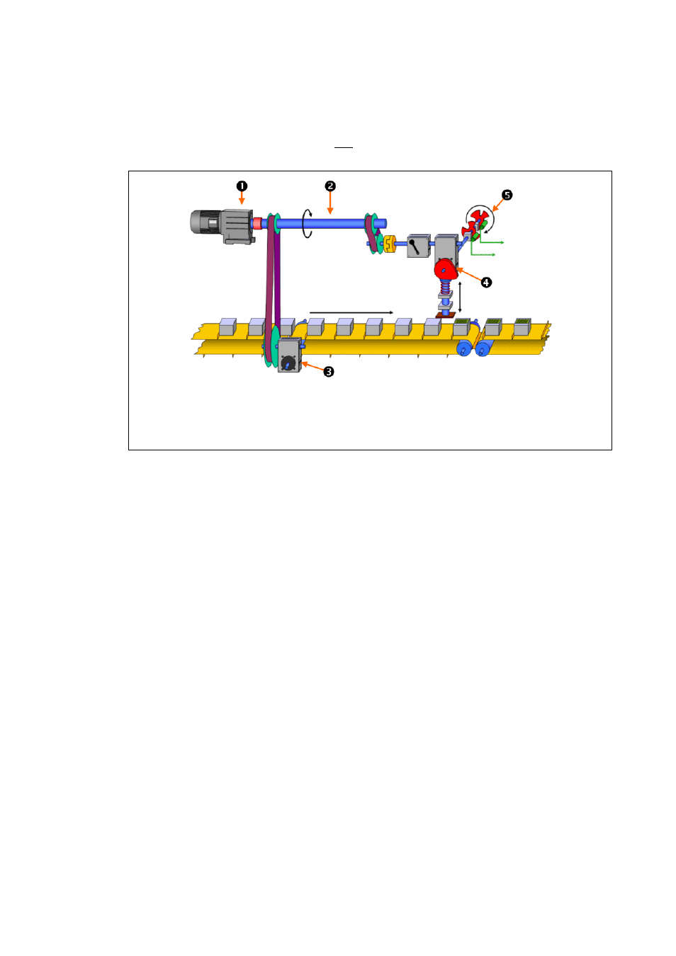
Principle of the mechanical shaft: fixed synchronisation of the tools with regard to each other
• A drive with a virtual master or a real master (encoder) can generate the master angle and
transfer it to the other drives, which then comply with this master angle.
• The master angle/machine cycle is usually shown "modulo" with a cycle of 0 to 360°. All
movements are exactly synchronised with this master angle.
• The tools can feature an optional measuring system ("limited", "unlimited", or "modulo"
traversing range).
• For the interconnected drives, the busbar structure is used almost exclusively.
Main drive (master)
Line shaft (here: one revolution = 360° = one production cycle)
Slave drive 1: Feed control tape (non-linear indexing unit)
Slave drive 2: stamp drive (mechanical cam)
Cam discs for generating control-cam signals (2 cam tracks)