5 process data objects, Process data objects, Process data objects ( 226) – Lenze Engineer v2.21 User Manual
Page 226: Inserting & configuring a network
Inserting & configuring a network
Process data objects
226
Lenze · Engineer · 2.13 EN - 10/2014
_ _ _ _ _ _ _ _ _ _ _ _ _ _ _ _ _ _ _ _ _ _ _ _ _ _ _ _ _ _ _ _ _ _ _ _ _ _ _ _ _ _ _ _ _ _ _ _ _ _ _ _ _ _ _ _ _ _ _ _ _ _ _ _
9.5
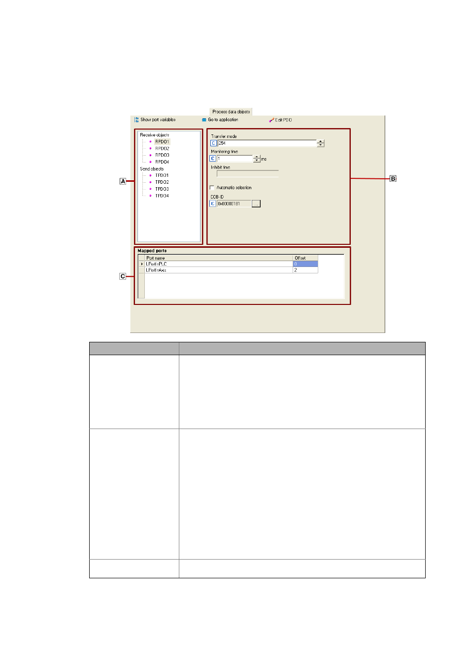
Process data objects
The Process data objects tab shows the current available process data objects for a node.
Area
Info
Process data objects
Display of all process data objects for the node selected, divided into send and
receive process data objects.
The number and name of each process data object depends on the device in
question.
If a process data object has been marked as "manual", a lock is shown in the icon next
to the corresponding process data object. Manual or automatic is indicated by
means of the Automatic allocation control field in the Transfer parameters area.
The network generator is only available for establishing a connection if the
Automatic allocation control field has been highlighted
.
Transfer parameters
Depending on the process data object selected, the associated transfer parameters
are displayed here. The selection and editing of the fields depends on the send and
receive process data objects as well as on the support for this function provided by
the node itself.
COB-ID selection field
Normally, the COB-ID for an interconnection is allocated by means of a generation
run ToolsBuild project.
If a process data object is required for an interconnection, a valid COB-ID is entered
for the sender and all receivers.
If a process data object is not used, it can be inhibited by setting bit[31].
Automatic allocation selection field
If you want to force sending or receiving of a process data object, you can do so by
deselecting the Automatic allocation control field and specifying the desired COB-
ID.
Mapped ports
Here all mapped ports are shown. The Offset column reflects the byte offset within
the process data object.