2 synchronisation of the tools with a material, Defining the system functionality – Lenze Engineer v2.21 User Manual
Page 184
Defining the system functionality
Creating an interconnection via the electrical shaft
184
Lenze · Engineer · 2.13 EN - 10/2014
_ _ _ _ _ _ _ _ _ _ _ _ _ _ _ _ _ _ _ _ _ _ _ _ _ _ _ _ _ _ _ _ _ _ _ _ _ _ _ _ _ _ _ _ _ _ _ _ _ _ _ _ _ _ _ _ _ _ _ _ _ _ _ _
8.14.2
Synchronisation of the tools with a material
In the case of this relative coupling, the tools are not synchronised with each other but with the
material path (e.g. by means of a touch probe sensor). Therefore in such applications, a master
speed is needed.
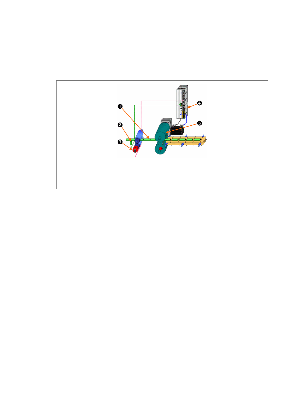
[8-10] Principle: mark-controlled synchronisation of the tool to the material
• The master speed is either taken from the material path via an encoder or is stipulated in
advance by the drive that determines the speed (virtual master).
• The tools rotate and are therefore modulo with a fixed modulo cycle.
• The material is modulo with a variable cycle (is measured if necessary, e.g. in the case of foil).
• The curves are created for a nominal cycle/register.
• Adaptation to the measured cycle is carried out individually for each tool in the drive by
means of its own sensors during the runtime.
Mark track on the material
Mark sensor for detecting the register on the material (touch probe evaluation within the controller)
Master value encoder (TTL incremental encoder; supplies speed by means of digital frequency input)
Controller with electronic cam technology
Orientation of the tool to the material (here: to the cutting mark)