2 step 2: entering curves, Step 2: entering curves, Appendix – Lenze Engineer v2.21 User Manual
Page 285
Lenze · Engineer · 2.13 EN - 10/2014
285
Appendix
Creating cam data with the »Cam Editor«
_ _ _ _ _ _ _ _ _ _ _ _ _ _ _ _ _ _ _ _ _ _ _ _ _ _ _ _ _ _ _ _ _ _ _ _ _ _ _ _ _ _ _ _ _ _ _ _ _ _ _ _ _ _ _ _ _ _ _ _ _ _ _ _
14.3.2.2
Step 2: Entering curves
You describe the motion profile or the characteristic by entering graphic objects in the Worksheet.
Tip!
When using the »Cam Designer«:
Only define the basic conditions that are absolutely necessary. Limit the length of the stop
positions to the minimum possible length.
The more degrees of freedom the »Cam Designer« has during the automatic generation,
the smoother the resulting curves will be. If required, also line segments are added to the
polynomials.
At the beginning, start with a minimum number of basic conditions. Then trigger
automatic connection of the segments in the curve mode. After this, add further basic
conditions, if necessary, in the object entry mode.
How to enter graphic objects in the worksheet:
1.
Change to the object input mode.
2. Select graphic object in the Toolbar or in the Draw menu.
3. Draw selected object in the worksheet.
Drawing a point:
• Move the mouse pointer to the desired coordinates.
• Press the left-hand mouse button.
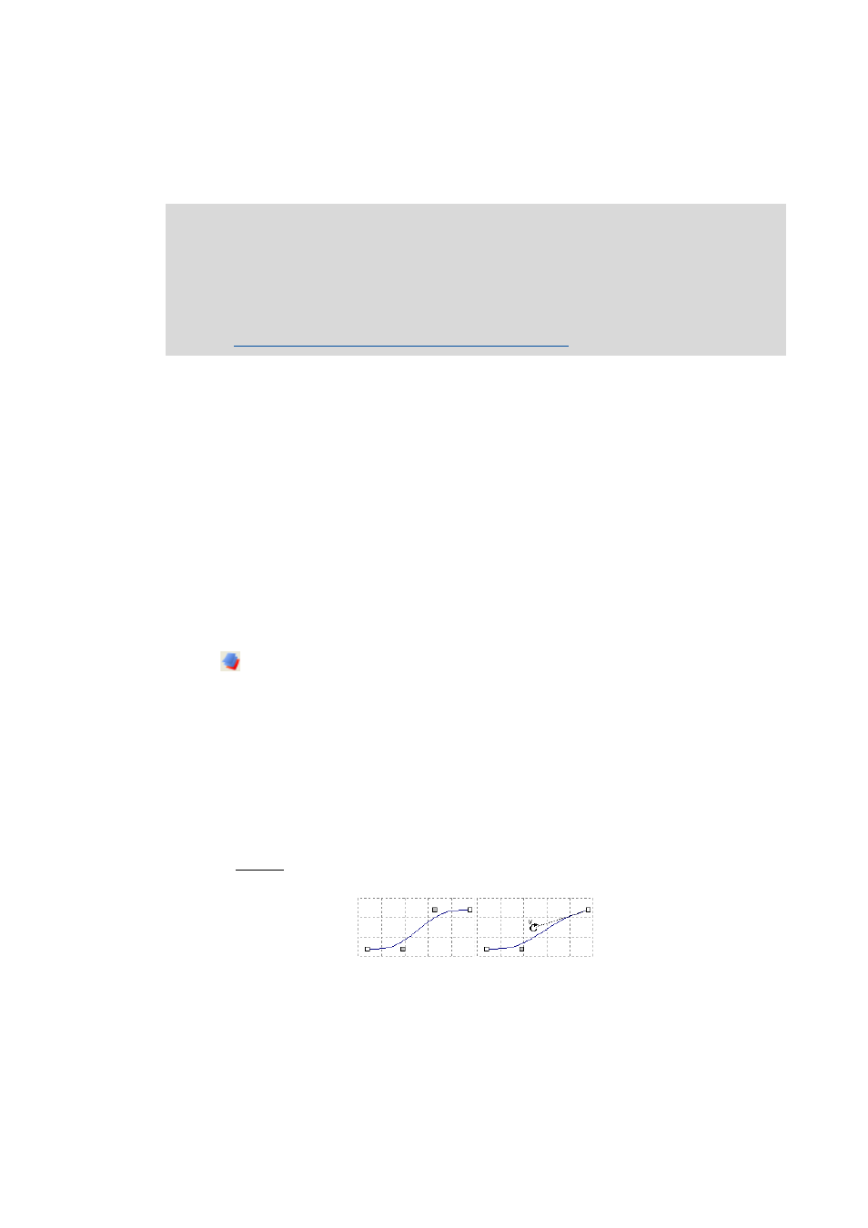
Drawing other objects (line, polynomial, etc.):
• Move the mouse pointer to the desired starting point.
• Draw mouse pointer to the desired end point while keeping the left mouse button
pressed.
• At the light grey square, you can then alter the speed at a boundary value.
The shape and position of an object can still be altered later by dragging it with the mouse.
Note!
The »Cam Editor« needs a closed curve in order to be able to create cam data in the curve
mode.
The »Cam Designer« only requires the entry of the basic conditions. The segments can
then be joined automatically by the »Cam Designer«.
Step 3: Triggering automatic connection of segments