3 vertical settings, Vertical settings, Device functions with active online connection – Lenze Engineer v2.21 User Manual
Page 114
Device functions with active online connection
Data logger
114
Lenze · Engineer · 2.13 EN - 10/2014
_ _ _ _ _ _ _ _ _ _ _ _ _ _ _ _ _ _ _ _ _ _ _ _ _ _ _ _ _ _ _ _ _ _ _ _ _ _ _ _ _ _ _ _ _ _ _ _ _ _ _ _ _ _ _ _ _ _ _ _ _ _ _ _
7.7.1.3
Vertical settings
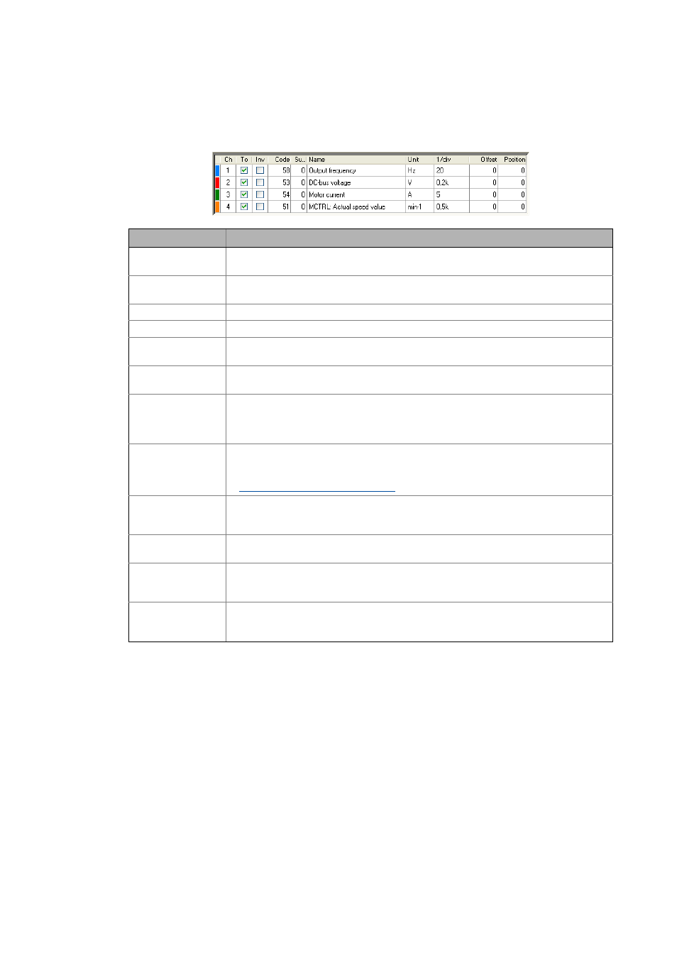
The parameters to be recorded are configured via the list field below the diagram:
Column
Meaning
-
Curve colour for the representation in the diagram
• Double-click this field to open the Colour dialog box for selecting another curve colour.
Ch
Channel number
• Read only
On
On/off
Inv
Inversion on/off
Code
Code of the parameter to be recorded
• Read only
Subcode
Subcode of the parameter to be recorded
• Read only
Device
Name of the device that contains the parameter to be recorded.
•
»Engineer« From »Engineer» V2.10
, the data logger is also available for the upper project
element, for system modules, and for axes for a cross-device recording. In this case, the
list field additionally contains the "device" column.
Name
Name of the parameter to be recorded
• Double-click this field to open the Insert channel dialog box for selecting the parameter
to be recorded.
Selecting the variables to be recorded ( 116)
Unit
Scaling
• Double-click this field to open the Scaling dialog box for setting the scaling for the
parameter to be recorded.
1/Div
Vertical scale factor
• Click this field to open the list field for selecting the vertical scale factor.
Offset
Offset value
• The offset value depends on the scale factor and is marked by a dashed line in the curve
colour in the left-most position of the diagram.
Position
Position value
• The position value is independent of the scale factor and marked by a line in the left-most
position of the diagram.