5 measuring systems, Defining the system functionality – Lenze Engineer v2.21 User Manual
Page 194
Defining the system functionality
Creating an interconnection via the electrical shaft
194
Lenze · Engineer · 2.13 EN - 10/2014
_ _ _ _ _ _ _ _ _ _ _ _ _ _ _ _ _ _ _ _ _ _ _ _ _ _ _ _ _ _ _ _ _ _ _ _ _ _ _ _ _ _ _ _ _ _ _ _ _ _ _ _ _ _ _ _ _ _ _ _ _ _ _ _
8.14.5
Measuring systems
In a drive controller with a cam function, there are always at least two measuring systems: the
measuring system for stipulation of the master values (master) and the measuring system for the
drive axis (slave).
• The two measuring systems are merged with each other by means of the motion profile (curve),
with account being taken of the mechanical data (machine parameters).
[8-13] Example: Controller with cam function and two different measuring systems
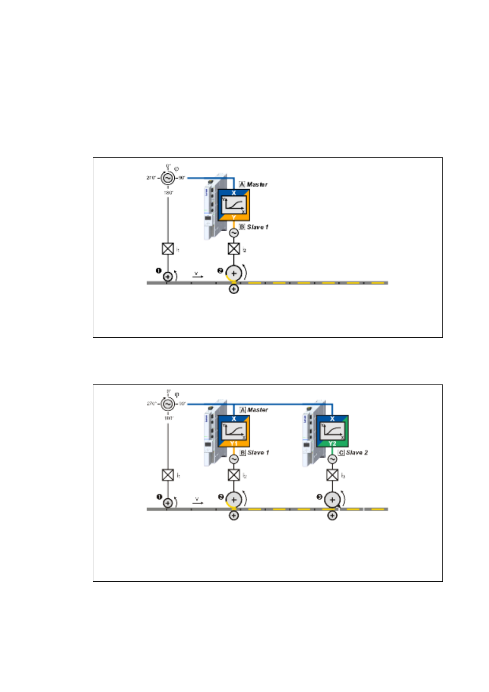
• If several drive controllers are interconnected, other measuring systems are added in
accordance with the number of drive axes:
[8-14] Example: Controller interconnection with cam function and three different measuring systems
Master measuring system
Measuring system, slave 1
Encoder for the master value selection (real master)
Drive axis (slave 1)
Master measuring system
Measuring system, slave 1
Measuring system, slave 3
Encoder for the master value selection (real master)
Drive axis 1 (slave 1)
Drive axis 2 (slave 2)