Lenze Engineer v2.21 User Manual
Page 46
Mapping the system structure in the »Engineer« project
46
Lenze · Engineer · 2.13 EN - 10/2014
_ _ _ _ _ _ _ _ _ _ _ _ _ _ _ _ _ _ _ _ _ _ _ _ _ _ _ _ _ _ _ _ _ _ _ _ _ _ _ _ _ _ _ _ _ _ _ _ _ _ _ _ _ _ _ _ _ _ _ _ _ _ _ _
Tip!
Name the individual system modules uniquely. Orient yourself on your real machine
structure in order to be able to clearly identify the individual project elements.
Inserting components
After the system structure has been represented in the form of system modules and axes, the
suitable components (inverters, motors, I/O systems, gearboxes, etc.) must be inserted:
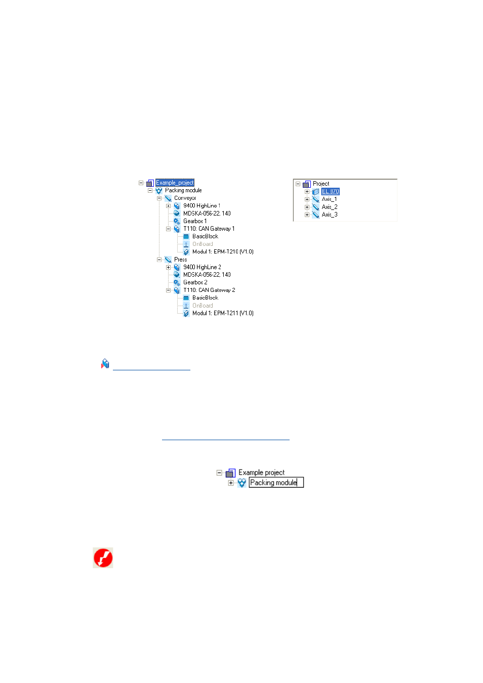
[5-1]
Examples of projects with different components
Tip!
For documentation purposes, every element in the Project view can be provided with notes
and file attachments (images, circuit diagrams, CAD data, etc.).
Documentation referring to the whole system can be attached to the Project root, for
instance.
Documentation - Add project details
If you select an element in the Project view and press the
the name of the element:
• Press the to accept the change, or the
Ambiguous designation
If the name of a component already exists in a project, it will be symbolised by the following icon:
.
• By specifying the Current designation and the Designations already assigned you can define a
New designation in order to be able to clearly identify the corresponding component in the
project.
Example 1: Two 9400 HighLine drive controllers
Example 2: EL 870 controller