Ez80® cpu registers in z80 mode, Ez80, Cpu registers in z80 mode – Zilog EZ80F916 User Manual
Page 20
eZ80
®
CPU
User Manual
UM007715-0415
Registers and Bit Flags
11
•
Interrupt Enable Flags (IEF1 and IEF2)—in the CPU, there are two interrupt enable
flags that are set or reset using the Enable Interrupt (EI) and Disable Interrupt (DI)
instructions. When IEF1 is reset to 0, a maskable interrupt cannot be accepted by the
CPU. The Interrupt Enable flags are described in more detail in
eZ80
®
CPU Registers in Z80 Mode
In Z80 mode, the BC, DE, and HL register pairs and the IX and IY
registers function as 16-bit registers for multibyte operations and indirect addressing. The
active Stack Pointer is the 16-bit Stack Pointer Short
register (SPS). The Program Counter register (PC) is also 16 bits long. The address is 24
bits long and is composed as {MBASE, ADDR[15:0]}. While the MBASE register is only
used during Z80 mode operations, it cannot be written while operating in this mode.
lists the CPU registers and bit flags during Z80 mode operation.
In Z80 mode, the upper byte (bits 23:16) of each multibyte register is
undefined. When performing 16-bit operations with these registers, the
application program cannot assume values or behavior for the upper byte. The upper
byte is only valid in ADL mode.
In Z80 mode, the upper byte of the I register, bits [15:8], is not used.
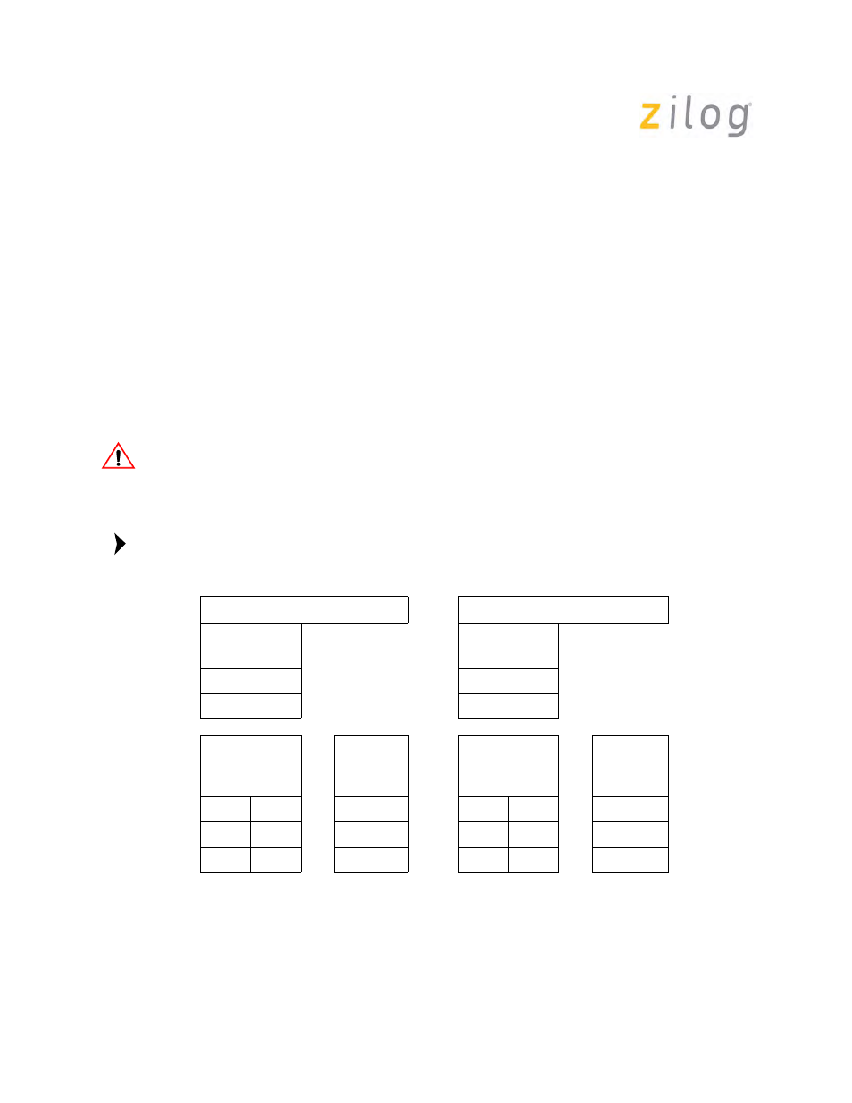
Table 1. CPU Working Registers in Z80 Mode
Main Register Set
Alternate Register Set
8-Bit
Registers
8-Bit
Registers
A
A’
F
F’
Individual
8-Bit
Registers
Or
16-Bit
Registers
Individual
8-Bit
Registers
Or
16-Bit
Registers
B
C
BC
B’
C’
BC’
D
E
DE
D’
E’
DE’
H
L
HL
H’
L’
HL’
Caution:
Note: