7 interrupt identificati, 8 system clock control r, 7 interrupt identification register (iir) -10 – Maxim Integrated MAXQ7667 User Manual
Page 54: 8 system clock control register (ckcn) -10, Maxq7667 user’s guide, 7 interrupt identification register (iir), 8 system clock control register (ckcn)
__________________________________________________________________________________________________________
4-10
MAXQ7667 User’s Guide
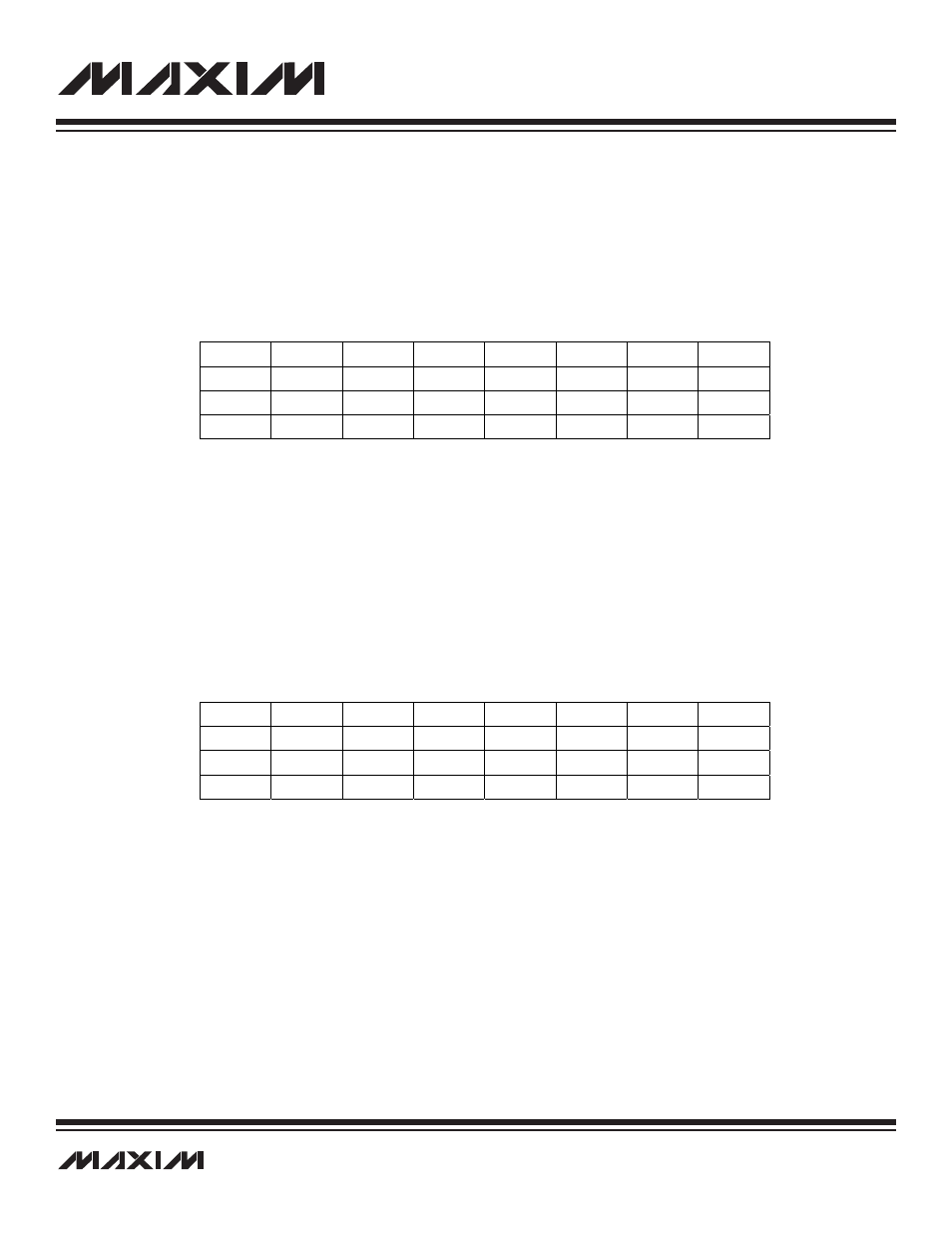
4.1.7 Interrupt Identification Register (IIR)
The first six bits in this register indicate interrupts pending in modules 0 to 5, one bit per module. The eighth bit, IIS, indicates a pend-
ing system interrupt, such as from the watchdog timer. The interrupt pending flags will be set only for enabled interrupt sources wait-
ing for service. The interrupt pending flag will be cleared when the pending interrupt sources within that module are disabled or when
the interrupt flags are cleared by software.
Register Description:
Interrupt Identification Register
Register Name:
IIR
Register Address:
Module 08h, Index 0Bh
Bit 7: Interrupt Identifier Flag for System Modules (IIS)
Bit 6: Reserved. Read 0, write ignored.
Bits 5 to 0: Interrupt Identifier Flag for Register Module 5 to 0 (II[5:0])
4.1.8 System Clock Control Register (CKCN)
The 8-bit CKCN register is part of the system register group and used to support system clock generation. It controls the system clock
speed and power management mode selection. See Section 5 for the description of this register.
Register Description:
System Clock Control Register
Register Name:
CKCN
Register Address:
Module 08h, Index 0Eh
Bit #
7
6
5
4
3
2
1
0
Name
IIS
—
II5
II4
II3
II2
II1
II0
Reset
0
0
0
0
0
0
0
0
Access
r
r
r
r
r
r
r
r
r = read
Note: This register is cleared to 00h on all forms of reset.
Bit #
7
6
5
4
3
2
1
0
Name
XTRC
—
RCMD
STOP
SWB
PMME
CD1
CD0
Reset
0
0
0
0
0
0
0
0
Access
rw
r
r
rw
rw
rw
rw
rw
r = read, w = write
Note: See bit descriptions in Section 15.