9 echo envelope lowpass, Maxq7667 user’s guide – Maxim Integrated MAXQ7667 User Manual
Page 295
17.3.9 Echo Envelope Lowpass Filter FIFO Control Register (LPFC)
Register Description:
Echo Envelope Lowpass Filter FIFO Control Register
Register Name:
LPFC
Register Address:
Module 05h, Index 0Ah
Bits 15 to 12: Lowpass Filter FIFO Interrupt Level (FFIL[3:0]). An interrupt is issued when the FIFO depth indicator FFDP reaches
the level set by FFIL[3:0] (excluding 000, which disables interrupt generation due to fill level, leaving only overflow interrupts to be
generated).
Bits 11 to 8: Lowpass Filter FIFO Depth (FFDP[3:0]). Indicates the number of samples in the FIFO (0 to 8). The FIFO is full when it
has eight data items in it (i.e., the 11th bit denotes FIFO full).
Bit 7: Lowpass Filter FIFO Overflow Indicator (FFOV). This is a sticky bit that indicates that a FIFO write has been attempted while
the FIFO was full (that data was blocked and is lost). An interrupt is generated on an overflow if the interrupt has been enabled.
Bits 6 to 4: Reserved. Read returns 0.
Bit 3: Lowpass Filter FIFO Load (FFLD). Writing a 1 to this bit loads LPFD into the LPFF FIFO if FFLS is set to 111. Writing a 0 has
no effect. This bit always reads 0.
Bits 2 to 0: Lowpass Filter FIFO Load Control Source Select (FFLS[2:0]). These bits select the source that initiates a FIFO load.
000 selects timer 0
001 selects timer 1
010 selects timer 2
011, 100, and 101 are reserved
110 selects continuous loading at each LPFRDY condition
111 selects FFLD bit
17-13
_________________________________________________________________________________________________________
MAXQ7667 User’s Guide
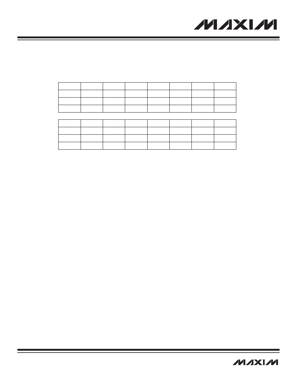
r = read, w = write
Note: LPFC is cleared to 0007h on all forms of reset.
Bit #
15
14
13
12
11
10
9
8
Name
FFIL3
FFIL2
FFIL1
FFIL0
FFPD3
FFDP2
FFDP1
FFDP0
Reset
0
0
0
0
0
0
0
0
Access
rw
rw
rw
rw
r
r
r
r
Bit #
7
6
5
4
3
2
1
0
Name
FFOV
—
—
—
FFLD
FFLS2
FFLS1
FFLS0
Reset
0
0
0
0
0
1
1
1
Access
r
r
r
r
rw
rw
rw
rw