3 triggering the burs, 3 burst generation example, 3 triggering the burst signal -20 – Maxim Integrated MAXQ7667 User Manual
Page 302: 3 burst generation example -20, Figure 17-4. burst pulse example -20, Maxq7667 user’s guide
17.4.2.3 Triggering the Burst Signal
Once all the register bits have been set to generate the frequency, duty cycle, and number of pulses, and enable the BURST pin, the
burst signal can be transmitted out through the BURST output pin by setting the burst start bit, BSTT (BPH.15) to 1. Once a burst
sequence is initiated, the sequence progresses to completion, always producing the exact number of whole pulses specified. BSTT
remains 1 during this time and automatically resets to 0 at the end of the last whole pulse. Changing BSTT to 0 in software is blocked
by the hardware.
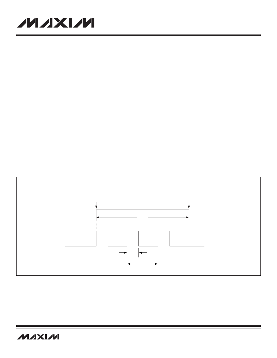
17.4.3 Burst Generation Example
The following example shows a burst signal with a frequency of 48kHz and a 45% duty cycle. The crystal frequency is 16MHz.
The register bits are set as follows:
BCKS = 0: Clock source is the PLL.
PLLC = 0b00: 16MHz crystal.
PLLF = 215: Sets the PLL to 15.36MHz, 16MHz x (215 + 768)/1024 = 15.36MHz.
BDIV = 0b1011: Divides the clock by 320; B
FREQ
= 15.36MHz/320 = 48kHz.
BPH = 144: 45% duty cycle, 144/320 = 0.45.
BPOL = 0: Output idles low with high going pulses.
BCNT = 3: One burst contains three pulses.
BGT = 0: Allow signal on the BURST pin.
BTRI = 0: Normal state for the BURST pin.
Burst Duration = 3/48kHz = 62.5µs
_________________________________________________________________________________________________________
17-20
MAXQ7667 User’s Guide
BSTT
THE BSTT BIT, WHEN SET TO 1, INITIATES THE BURST SEQUENCE.
ONCE SET TO 1, THIS BIT CAN ONLY BE SET TO 0 BY THE HARDWARE,
ONLY AFTER THE BURST SEQUENCE IS COMPLETE. ANY ATTEMPTS TO
CHANGE BSTT THROUGH SOFTWARE ARE IGNORED.
THE HARDWARE SETS BSTT TO 0 AT
THE COMPLETION OF THE BURST SEQUENCE ONLY.
BURST
62.5
µs
9.38
µs
(45%)
20.83
µs
(48kHz)
Figure 17-4. Burst Pulse Example