4 spi clocking modes, 4 spi clocking modes -14, Figure 9-5. spi clocking modes -14 – Maxim Integrated MAXQ7667 User Manual
Page 176: Maxq7667 user’s guide
__________________________________________________________________________________________________________
9-14
MAXQ7667 User’s Guide
Once the port is configured as an SPI bus slave, either polling or interrupts can be used to monitor the progress of the transfer cycle.
The STBY flag is set once a transfer cycle is initiated from the SPI master to the slave device. Once the transfer cycle is complete, the
SPIC flag is set and data should be read from the SPIB.
1)
Poll SPIC or use interrupts to monitor the status of the transfer cycle.
2)
Check to see the cause of the interrupt if interrupts used.
3)
Read the contents of the SPIB register and take the appropriate action to:
a. Interpret the data as an instruction or data.
b. Take the appropriate actions as deemed by the defined protocol used.
4)
Clear the SPIC flag by doing a bit write to 0.
5)
Write a new character to the SPIB in response to and in preparation for the next transfer cycle.
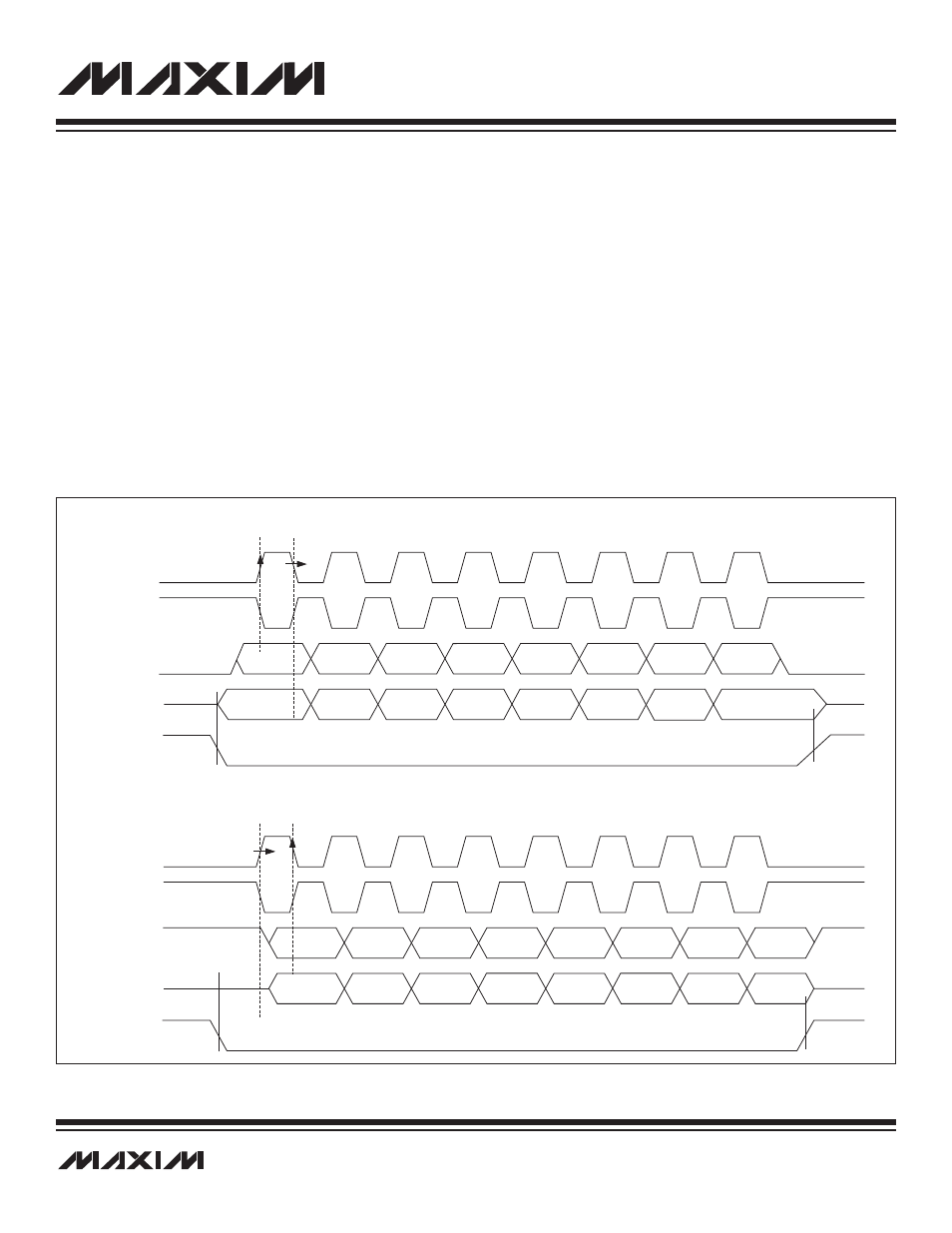
9.1.4 SPI Clocking Modes
The SPI bus is a full-duplex bus where data is simultaneously transmitted and received synchronous to the SPICK on the MISO and
MOSI data pins. The CKPHA and CKPOL bits control the SPICK data transfer mode when data is shifted and sampled on the serial
data bus. Figure 9-5 illustrates the four selectable SPI transfer modes. When CKPOL is cleared (0), the rising edge of SPICK is the
sampling edge; when CKPOL is set (1), the falling edge of SPICK is the active edge.
Figure 9-5. SPI Clocking Modes
SPICK (CKPOL = 0)
SPICK (CKPOL = 1)
MOSI
MISO
SS
SPICK (CKPOL = 0)
SPICK (CKPOL = 1)
MOSI
MISO
SS
SAMPLE
EDGE
SPI MODES 0 AND 3: CKPHA = 0
SPI MODES 1 AND 4: CKPHA = 1
SLAVE
ENABLE
SLAVE
ENABLE
SLAVE
DISABLE
SLAVE
DISABLE
SHIFT
EDGE
SAMPLE
EDGE
SHIFT
EDGE
MSB
6
6
6
6
5
5
5
5
4
4
4
4
3
3
3
3
2
2
2
2
1
1
1
1
LSB
LSB
LSB
LSB
MSB
MSB
MSB